Separable electrical interconnect with anisotropic conductive elastomer for translating footprint

a technology of anisotropic conductive elastomer and electrical interconnection, which is applied in the direction of coupling device connection, printed circuit aspects, printed circuit manufacturing, etc., can solve the problems of mounting under the device and on the back of the board, and achieve the effect of enhancing the stiffness of the adapter board

Inactive Publication Date: 2007-07-31
PARICON TECH
View PDF20 Cites 120 Cited by
  • Summary
  • Abstract
  • Description
  • Claims
  • Application Information

AI Technical Summary

Benefits of technology

[0008]The connector may also further comprise a flexible circuit element between the device and the ACE. The flexible circuit element may comprise electrical contacts on both sides electrically connected together through the circuit element thickness. The connector may still further comprise an insulating backfill between the adapter and the substrate to enhance the stiffness of the adapter board. The backfill may be epoxy. The device may further comprise a second layer of ACE between the adapter board and the device.

Problems solved by technology

This can result in a conflict with components mounted under the device and on the back of the board.

Method used


Image

  • Separable electrical interconnect with anisotropic conductive elastomer for translating footprint
  • Separable electrical interconnect with anisotropic conductive elastomer for translating footprint
  • Separable electrical interconnect with anisotropic conductive elastomer for translating footprint

Examples


Embodiment Construction

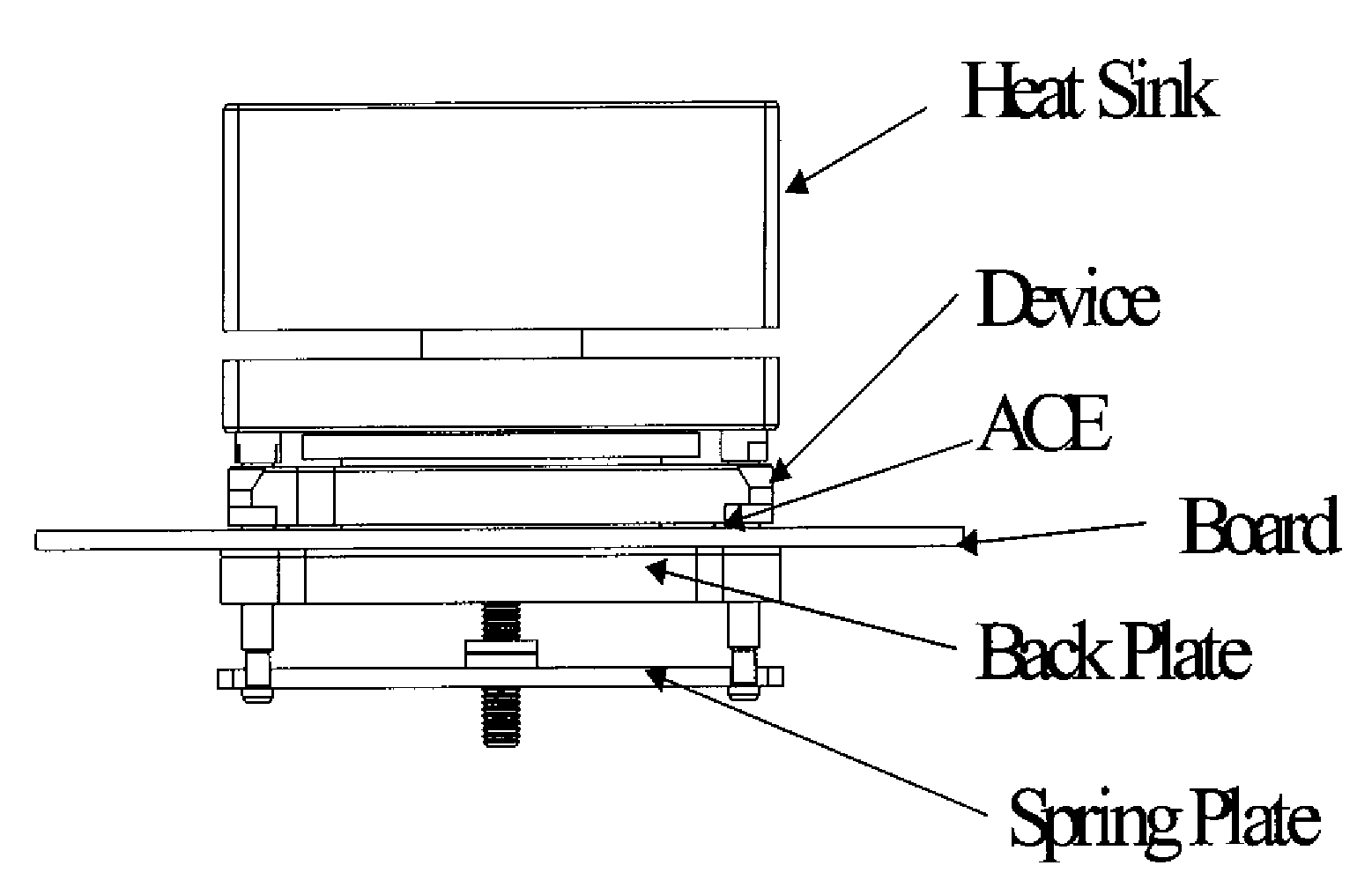
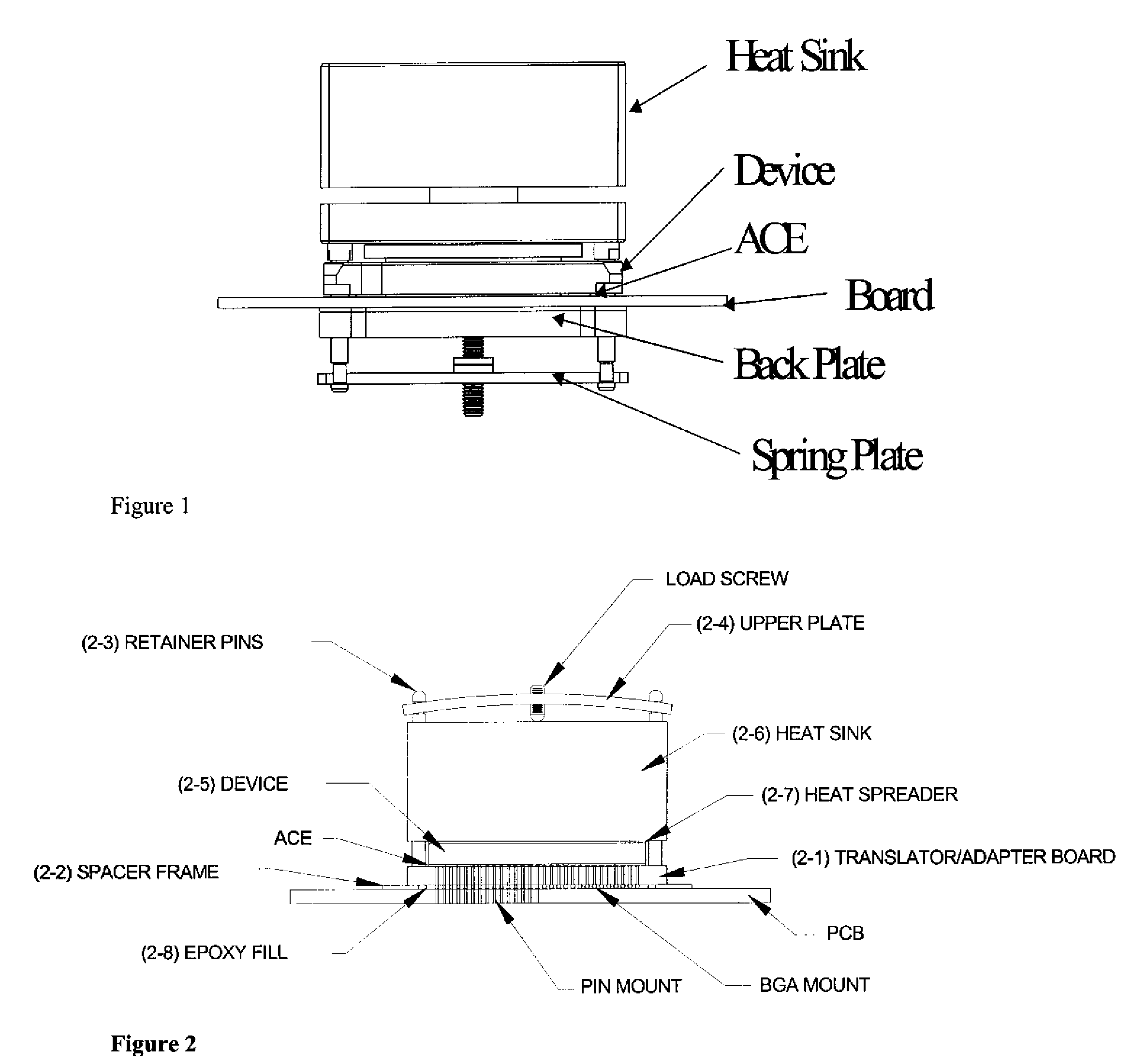
[0019]FIG. 2 details several aspects of one preferred embodiment of the invention. The aim of the invention is to accomplish a functional and separable electrical interconnection between electrical device 32 and substrate 34, which is typically a printed circuit board. There are many uses for such a separable electrical connector. One is in a fixture to test or burn-in computer chips. This requires that the chips be quickly and easily electrically connected to a board, and then removed and replaced with another chip after the appropriate test. Also shown in this drawing (for illustration purposes only) are two different types of typical electrical device output interconnection structures-ball grid array 50 and pin array 52. Typically, one or the other of these two would be used, never both. Both are illustrated to show that the device can accommodate either type of connection hardware.

[0020]The invention contemplates placing a relatively rigid adapter board 36 between device 32 and ...


PUM


Abstract

A separable electrical connector for electrically interconnecting an electrical device to a substrate. In one embodiment, the connector includes an adapter board electrically connected to the substrate, the adapter board having electrical contacts on both sides, and a layer of ACE between the electrical device and the adapter board. A mechanical structure is used to apply a compressive force on the ACE through the adapter board and the electrical device. In another embodiment, the connector includes a translator board having electrical contacts on both sides and electrical circuits within to expand the footprint of the fine pitch electrical device to the coarser pitch of the substrate. The connector further includes a layer of ACE between the translator board and the substrate.

Description

CROSS REFERENCE TO RELATED APPLICATION[0001]This application is a continuation-in-part of, and claims priority from, U.S. patent application Ser. No. 10 / 374,698 entitled “Separable electrical interconnect with anisotropic conductive elastomer and a rigid adapter” filed Feb. 26, 2003 now U.S. Pat. No. 7,077,659, to Weiss et al., the entire contents of which is incorporated by reference herein, and which is based upon and claims the benefit of priority from patent application Ser. No. 09 / 465,056 filed Dec. 16, 1999 and U.S. provisional application No. 60 / 359,618 filed Feb. 26, 2002, the entire contents of which are incorporated by reference herein.FIELD OF THE INVENTION[0002]This invention relates to a separable electrical connector for electrically connecting an electrical device to a substrate.BACKGROUND OF THE INVENTION[0003]Anisotropic Conductive Elastomer (ACE) is a composite of conductive metal elements in an elastomeric matrix that is normally constructed such that it conducts ...

Claims


Application Information

Patent Timeline
Patent Type & Authority Patents(United States)
IPC IPC(8): H01R12/00
CPCH01R13/2414H01R31/06H05K1/141H01R12/714H01R12/7076H01R12/7082H01R12/707H05K3/325H05K2201/0314H05K2201/049H05K2201/10325H05K2201/2009
Inventor WEISS, ROGER E.
Owner PARICON TECH
Why Eureka
Try Eureka