Blade clamping device

a clamping device and blade technology, applied in the direction of metal sawing devices, power driven reciprocating saws, manufacturing tools, etc., can solve the problems of inconvenient operation, large clamping device, inconvenient blade removal, etc., and achieve the effect of quick replacemen

Inactive Publication Date: 2007-08-07
POSITEC POWER TOOLS (SUZHOU) CO LTD
View PDF17 Cites 38 Cited by
  • Summary
  • Abstract
  • Description
  • Claims
  • Application Information

AI Technical Summary

Benefits of technology

[0003]The object of the present invention is to provide a blade (e.g. saw blade) clamping device which allows a blade to be replaced quickly.
[0006]The present invention provides an easily-operated blade clamping device with a simple structure and small size which permits a blade to be quickly released and replaced.
[0016]To prevent relative axial movement of the cylindrical rotatable sleeve and rotatable member, a retaining element (e.g. a circlip) may be mounted circumferentially on the interior surface at or near to the distal end of the cylindrical rotatable sleeve.
[0019]Preferably a first and a second protrusive stopper project radially inwardly from the proximal end of the cylindrical sleeve. In a particularly preferred embodiment, the device further comprises a limiting pin on the proximal head of the blade carrier, wherein said limiting pin engages the spiral surface along a path between the first protrusive stopper and the second protrusive stopper so as to limit the rotational range of the rotatable member in the clockwise and counter-clockwise direction.

Problems solved by technology

U.S. Pat. No. 5,165,173 discloses a saw in which the blade is fixed to the drive shaft by means of fixing screws so that it is very inconvenient to remove the saw blade.
In the blade clamping device of U.S. Pat. No. 5,324,052, the blade is pressed by a spring-loaded clamping piece against a slot wall but the clamping device is very big and its operation is inconvenient.

Method used


Image

  • Blade clamping device
  • Blade clamping device
  • Blade clamping device

Examples


Embodiment Construction

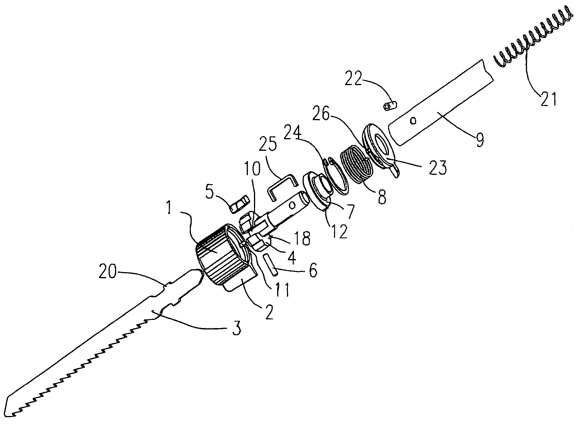
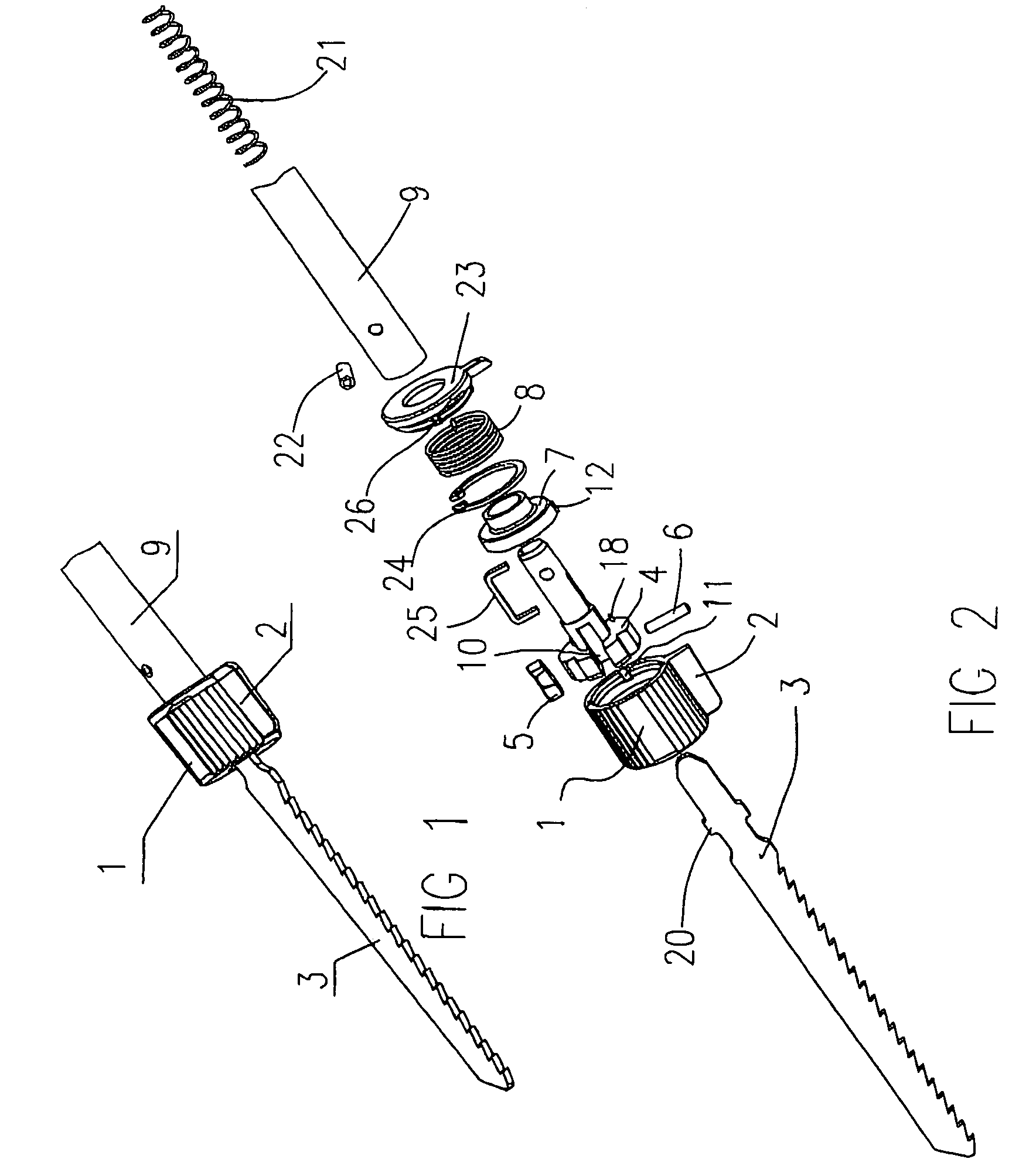
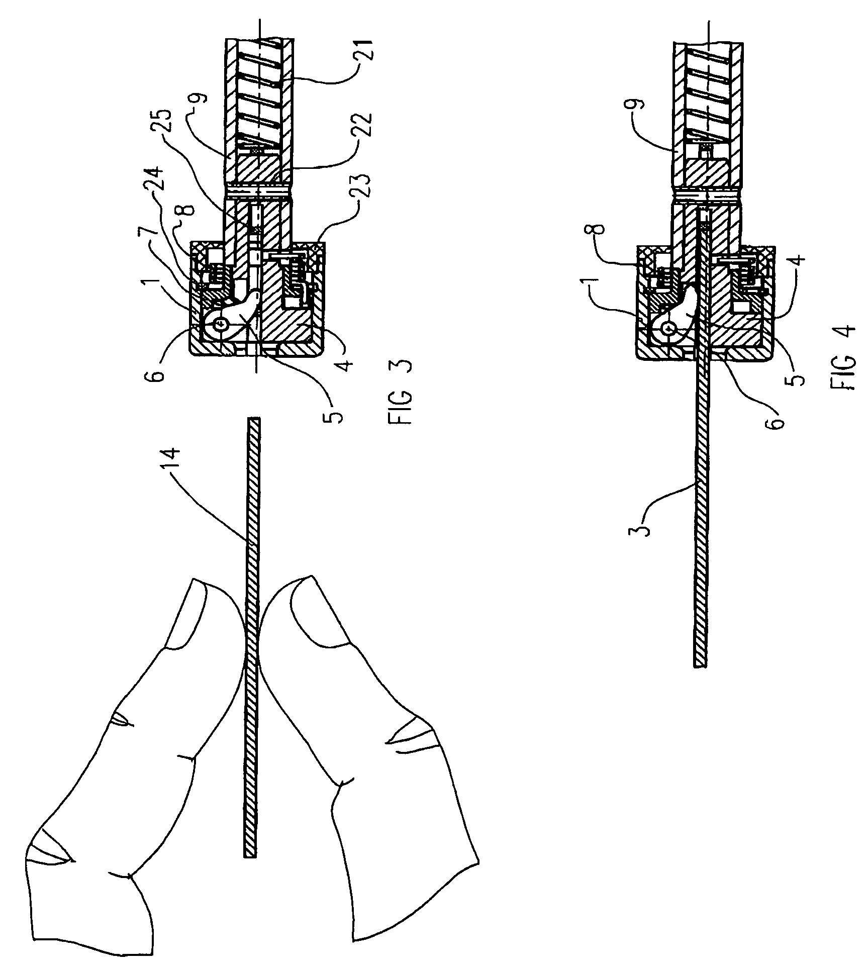
[0037]Referring to FIGS. 1 and 2, an embodiment of the blade clamping device of the invention is illustrated comprising a rotatable member 7 mounted coaxially within a cylindrical rotatable sleeve 1. The rotatable member 7 has a cylindrical main body 7a integrally formed at a proximal end with a cylindrical sleeve 7b. A protrusive rib 12 extends axially along the exterior surface of the cylindrical sleeve 7b (see FIG. 9) and a second retaining groove 17 extends axially along the interior surface of the cylindrical rotatable sleeve 1 (see FIG. 5). The protrusive rib 12 fits into the second retaining groove 17 to securely retain the rotatable member 7 and the cylindrical rotatable sleeve 1 together. Additionally a circlip 24 is mounted in a groove formed on the interior surface of the cylindrical rotatable sleeve 1 and engages the cylindrical sleeve 7b so as to retain the rotatable member 7 axially within the cylindrical rotatable sleeve 1 (i.e. the circlip 24 prevents axial movement)...


PUM

PropertyMeasurementUnit
forceaaaaaaaaaa
irregular shapeaaaaaaaaaa
sizeaaaaaaaaaa

Abstract

The present invention relates to a quick-change saw blade clamping device which includes an output shaft, a cylindrical rotatable sleeve and a torsion spring. The output shaft is coupled to a blade carrier which is disposed within the cylindrical rotatable sleeve. A rotatable member is disposed within the cylindrical rotatable sleeve. A locking member pivotally connected to the blade carrier lies in a guide groove which is formed on the blade carrier. A spiral surface is formed on the front end of the rotatable member. When the cylindrical rotatable sleeve is manually rotated, the spiral surface urges the locking member to press the blade into a locking position. The present invention provides an easily-operated clamping device of simple structure and small size.

Description

FIELD OF THE INVENTION[0001]The present invention relates to a blade clamping device for clamping the blade of (for example) a power saw such as a jigsaw or reciprocating saw.BACKGROUND[0002]CN-A-1217675 discloses a blade clamping device which disadvantageously needs to be riveted together. U.S. Pat. No. 5,165,173 discloses a saw in which the blade is fixed to the drive shaft by means of fixing screws so that it is very inconvenient to remove the saw blade. In the blade clamping device of U.S. Pat. No. 5,324,052, the blade is pressed by a spring-loaded clamping piece against a slot wall but the clamping device is very big and its operation is inconvenient.SUMMARY OF THE INVENTION[0003]The object of the present invention is to provide a blade (e.g. saw blade) clamping device which allows a blade to be replaced quickly.[0004]Thus viewed from one aspect the present invention provides a blade clamping device for clamping a blade comprising a cylindrical rotatable sleeve having a proxima...

Claims


Application Information

Patent Timeline
Patent Type & Authority Patents(United States)
IPC IPC(8): B27B3/30B27B19/09B23D51/10
CPCB23D51/10Y10T279/17717Y10T279/17914Y10T279/17769Y10T83/9481
Inventor SHUHUA, SANG
Owner POSITEC POWER TOOLS (SUZHOU) CO LTD
Why Eureka
Try Eureka