
Safety module and measuring arrangement with safety module

a safety module and safety module technology, applied in the field of safety modules, can solve the problems of route failure in the case of the installed base of the measurement transmitter or in the case of devices previously released for production, and achieve the effect of ensuring the safety of the devi

Inactive Publication Date: 2007-08-07
ENDRESS HAUSER FLOWTEC AG
View PDF10 Cites 1 Cited by
  • Summary
  • Abstract
  • Description
  • Claims
  • Application Information

AI Technical Summary

Benefits of technology

[0009]An object of the present invention is to improve the safety of conventional measurement transmitters.
[0025]The switching point for the pressure switch is selected such that, in the process-pressure ranges approved for the safety module, it produces with certainty an error report upon the failure of the first seal, but prevents false error signals. The switching point should thus lie outside the fluctuation range of the normal environmental pressure at the installation site of the sensor, or, respectively, outside the fluctuation range of the pressure inside the transmitter housing due to fluctuations in temperature. A suitable switching point can, for example, lie at an absolute pressure of 1.3 bar, 1.5 bar, or 2 bar, and / or at a gage pressure relative to ambient pressure, of 0.3 bar, 0.5 bar, or 1.0 bar. In order to provide as few openings in the module housing as possible, absolute pressure switches and absolute pressure sensors are presently preferred as leak detectors, because these do not require a reference air canal. In the case of transmitter housings with ventilation openings, which communicate with the pressure switch, the switching point can lie substantially lower, for example at an absolute pressure of 1.2 bar, and / or at a gage pressure, relative to ambient pressure, of 0.1 or 0.2 bar.

Problems solved by technology

This route, however, still fails in the case of the installed base of measurement transmitters or in the case of devices previously released for production.

Method used


Image

  • Safety module and measuring arrangement with safety module
  • Safety module and measuring arrangement with safety module
  • Safety module and measuring arrangement with safety module

Examples


Embodiment Construction

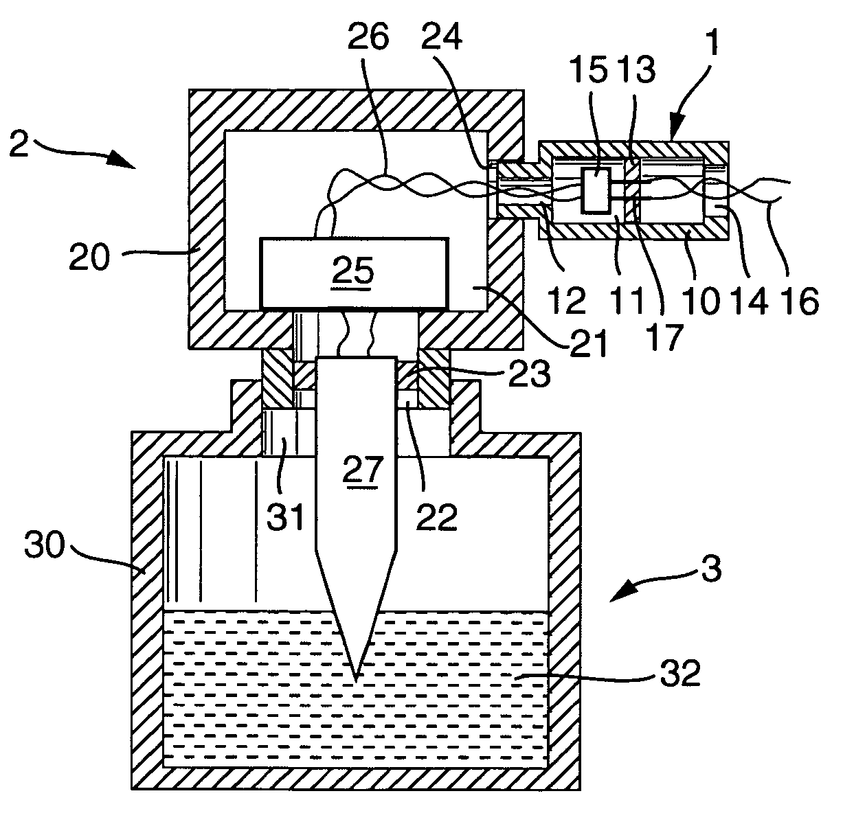
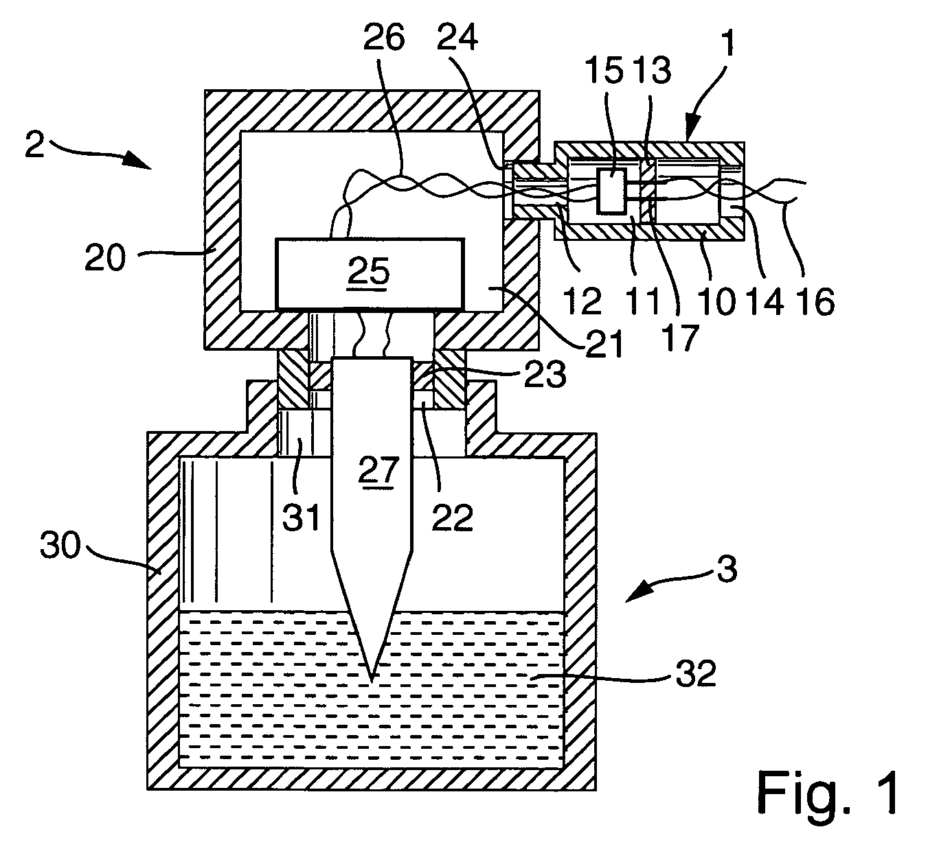
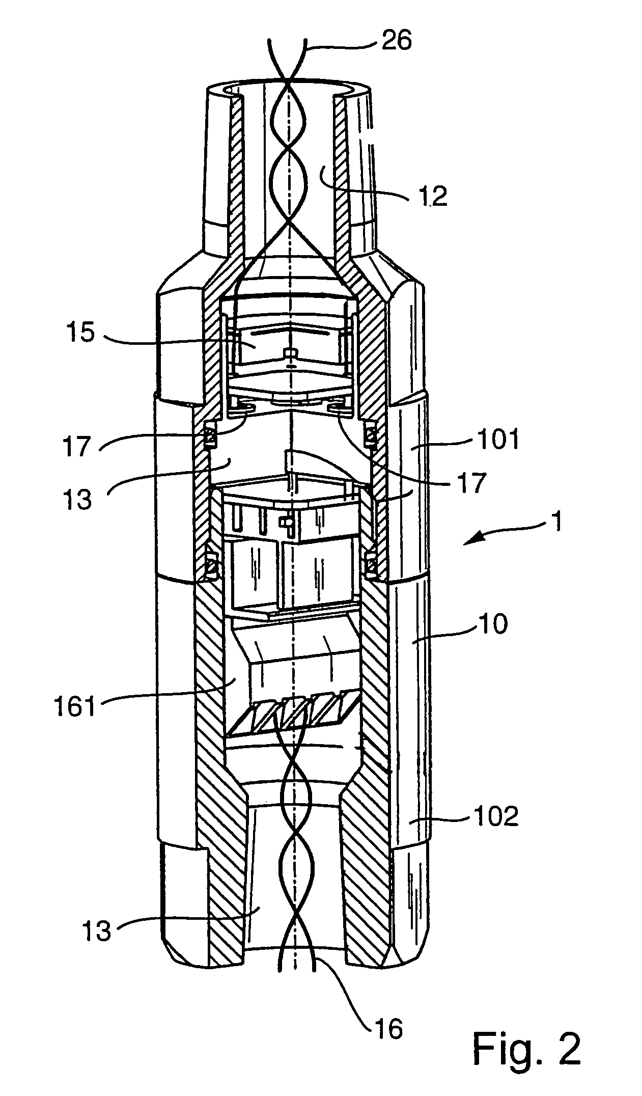
[0049]The structure of the measuring arrangement according to the invention is explained on the basis of FIG. 1. The measuring arrangement includes a measuring transmitter for registering a process parameter, for example a temperature. The transmitter 2 has a housing 20, which defines in its interior at least one chamber 21, which is connected with the surroundings of the housing by means of a first opening 22 and a second opening 24. In the first opening 22, a temperature sensor 27 is arranged, which registers the temperature of a medium 32 in a container 30 of a process plant 3. In this connection, the transmitter 2 is installed in the container-opening 31 of the container.

[0050]Between the temperature sensor 27 and the cylindrical wall of the first opening 22 of the housing, a first seal 23 is arranged, which seals the chamber 21 against the penetration of the medium through the first opening 22. In this respect, a section of the contamination path from the container 30 of the pr...


PUM


Abstract

A measuring arrangement, including: a measuring transmitter with a sensor for registering a property of a medium and for issuing a primary signal dependent on the property; a transmitter housing, with at least one chamber and a first opening on the side facing the medium as well as a second opening, with a first contamination path section extending between the openings through the chamber; a first seal, which interrupts the first contamination path section; a circuit in the chamber, for processing the primary signal and producing an output signal, which is issued over a first signal path section through the second opening; a safety module, which includes: a module housing with at least one module chamber, having a first module opening on the side facing the transmitter and a second module opening, wherein a second contamination path section reaches from the first module opening at least as far as into the module chamber; at least a second seal, which interrupts the second contamination path section; and a second signal path section; wherein the safety module is connectable with the transmitter, such that the contamination path sections and signal path sections connect each to one another; and a leak detector, which monitors a contamination path section between the two seals.

Description

FIELD OF THE INVENTION[0001]The present invention relates to a safety module, especially a safety module for measurement transmitters, as well as to a measuring arrangement having such a safety module.BACKGROUND OF THE INVENTION[0002]Measurement transmitters are frequently used to monitor a process parameter of a medium. Process parameters can be, for example, but not limited to, pressure, fill level, flow rate, pH, temperature. Measurement transmitters of this type have the following features:[0003]a sensor for registering a parameter of a medium, with the sensor issuing a primary signal dependent on the parameter;[0004]a transmitter housing, which defines at least one chamber in its interior, and which has a first opening on the side facing the medium, and a second opening; and[0005]an electronic circuit, which is arranged in the at least one chamber, with the circuit processing the primary signal of the sensor, and producing an output signal, which is issued over a signal path ex...

Claims


Application Information

Patent Timeline
IPC IPC(8): G01M3/00G01D11/24G01L9/00G01L19/14
CPCG01L19/0084G01L19/14G01L19/141
Inventor RENK, PETERKLOTZ-ENGMANN, GEROLDHUGEL, MICHAEL
Owner ENDRESS HAUSER FLOWTEC AG
Learn More