
Miter saw

a technology of miter saws and miters, which is applied in the field of miter saws, can solve the problems of reducing the cutting capacity reducing the cutting capacity, and increasing the cost of the miter saw

Inactive Publication Date: 2007-08-07
BLACK & DECKER INC
View PDF19 Cites 36 Cited by
  • Summary
  • Abstract
  • Description
  • Claims
  • Application Information

AI Technical Summary

Benefits of technology

[0010]In accordance with the present invention, an improved miter saw is employed. The miter saw includes a base assembly, a rotatable table rotatably connected to the base assembly and having a plane, a saw assembly including a motor and a blade disposed

Problems solved by technology

Typically, the cutting capacity of a miter saw is limited because of its blade size and / or geometry.
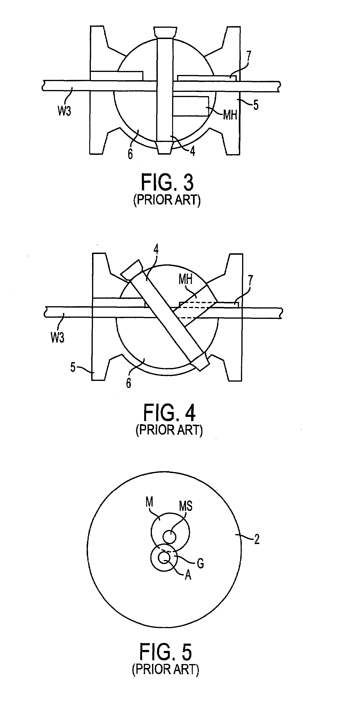
However, when the miter saw is mitered rightwardly, as shown in FIG. 4, the motor housing MH contacts the workpiece W3, restricting the cutting capacity.
But these are also more expensive, etc.

Method used


Image

  • Miter saw
  • Miter saw
  • Miter saw

Examples


Embodiment Construction

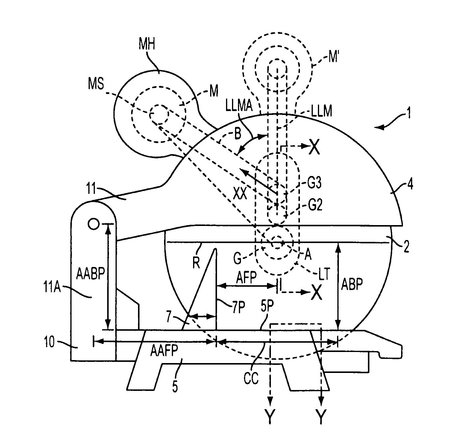
[0048]The invention is now described with reference to the accompanying figures, wherein like numerals designate like parts. FIG. 6 shows a first embodiment of the inventive miter saw. Referring to FIG. 6, the miter saw 1 has a base assembly 5, including a rotatable table 6 rotatably connected to the base assembly 5, a saw assembly including a motor M and a blade 2 driven by the motor M, and a pivot arm 11 pivotally attached to the table 6 via pivot junction 10 and supporting the saw assembly, allowing a user to move the saw assembly towards and away from the base assembly 5 for cutting a workpiece. Preferably, both the base assembly 5 and table 6 are coplanar. The height TH of the table plane 6P and / or base plane 5P is about 3.5 inches. Such height will allow a user to place boards commonly known as “four by fours” (which have a height and width of about 3.5 inches) next to base assembly 5 for supporting a workpiece thereon. Preferably, a lower guard 3 for covering the lower part o...


PUM

PropertyMeasurementUnit
Angleaaaaaaaaaa
Distanceaaaaaaaaaa
Distanceaaaaaaaaaa

Abstract

The miter saw includes a base assembly, a rotatable table rotatably connected to the base assembly and having a plane, a saw assembly including a motor and a blade disposed on an arbor, and a pivot arm pivotally attached to the table and supporting the saw assembly. The motor preferably drives a belt, which drives a first gear. The first gear meshes with an idler gear, which in turn meshes with a gear disposed on the arbor.

Description

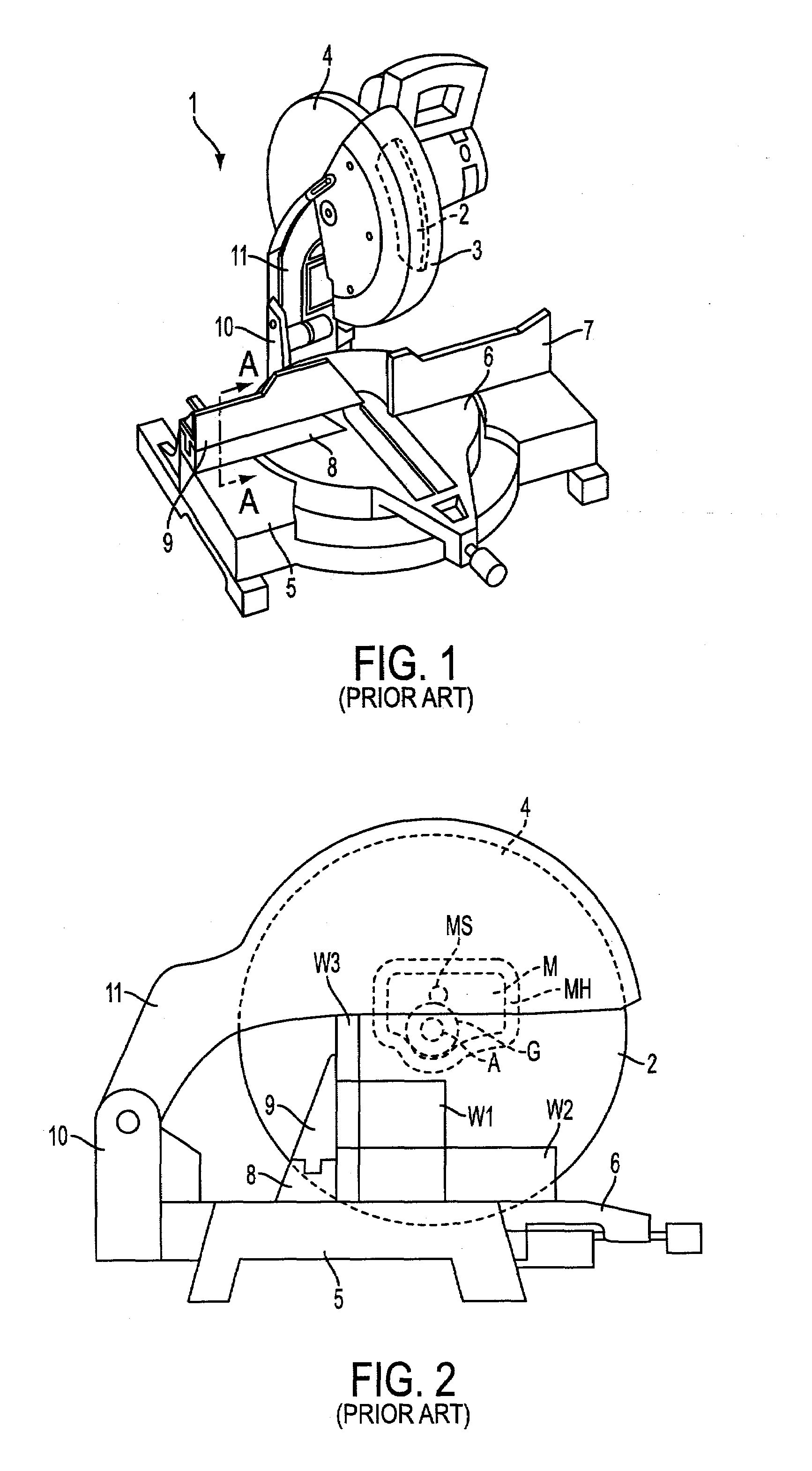
CROSS-REFERENCE TO RELATED APPLICATIONS[0001]This application derives priority under 35 USC §119(e) from U.S. application Ser. No. 60 / 267,371, filed Feb. 8, 2001, now abandoned.FIELD OF THE INVENTION[0002]This invention relates generally to miter saws.BACKGROUND OF THE INVENTION[0003]As shown in FIGS. 1-5, a typical miter saw 1 has a base assembly 5, including a rotatable table 6 rotatably connected to the base assembly 5, a saw assembly including a motor M and a blade 2 driven by the motor M, a pivot arm 11 pivotally attached to the table 6 via pivot junction 10 and supporting the saw assembly, allowing a user to move the saw assembly towards and away from the base assembly 5 for cutting a workpiece.[0004]Lower blade guard 3 typically covers the lower side of the blade 2, while upper blade guard 4 typically covers the upper side of the blade 2. Typically miter saw 1 would have a guard opening mechanism that moves lower blade guard 3 as the saw assembly is pivoted towards the base a...

Claims


Application Information

Patent Timeline
IPC IPC(8): B26D1/14B27B27/06B27B5/00B23D45/04B23D47/02B23D47/12B27B5/29B27B27/04
CPCB23D45/044B27B5/29Y10T83/762Y10T83/7726Y10T83/7705Y10T83/7697Y10T83/8773Y10T83/849Y10T83/7788Y10T83/7593B23D45/048
Inventor MEREDITH, DARYL S.KAYE, JR., THOMAS R.BLUDIS, THOMAS TREVORKENYON, MARIA I.STUMPF, WILLIAM R.O'BANION, MICHAEL L.OKTAVEC, CRAIG A.WRIGHT, STUART J.BRUNSON, MARK E.PUSCHMANN, CARRIE L.
Owner BLACK & DECKER INC
Learn More