
Channel installation device

a technology for installing devices and drainage channels, which is applied in the direction of groynes, applications, ways, etc., can solve the problems of laborious manual adjustment of the segments on the support rods, heavy and difficult to manipulate, and more workers

Inactive Publication Date: 2007-08-07
ACO POLYMER PRODS
View PDF38 Cites 13 Cited by
  • Summary
  • Abstract
  • Description
  • Claims
  • Application Information

AI Technical Summary

Benefits of technology

The cradle assembly facilitates quick, precise, and efficient installation of drainage channels, reducing labor requirements and ensuring accurate alignment, thereby minimizing leaks and ensuring a smooth transition between channel segments.

Problems solved by technology

Because polymer concrete drainage channel sections can be heavy and difficult to manipulate, manual adjustment of the segments on the support rods is generally labor intensive, often requiring two or more workers.

Method used


Image

  • Channel installation device
  • Channel installation device
  • Channel installation device

Examples


Embodiment Construction

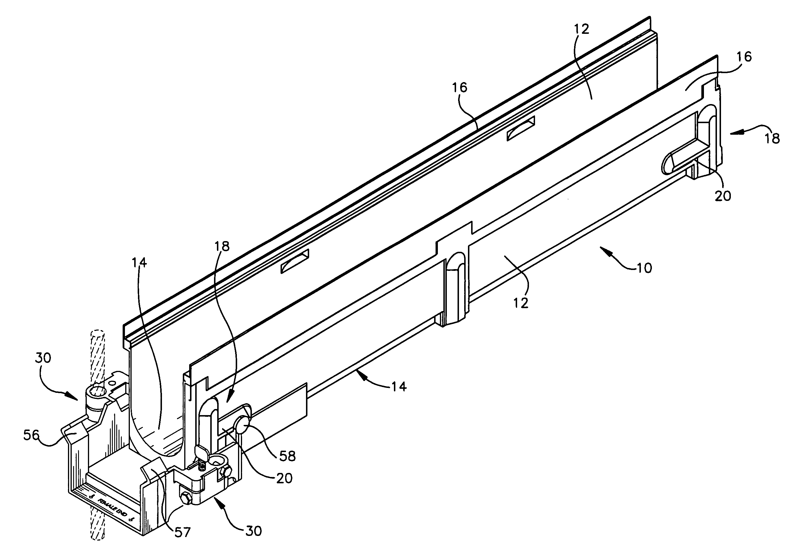
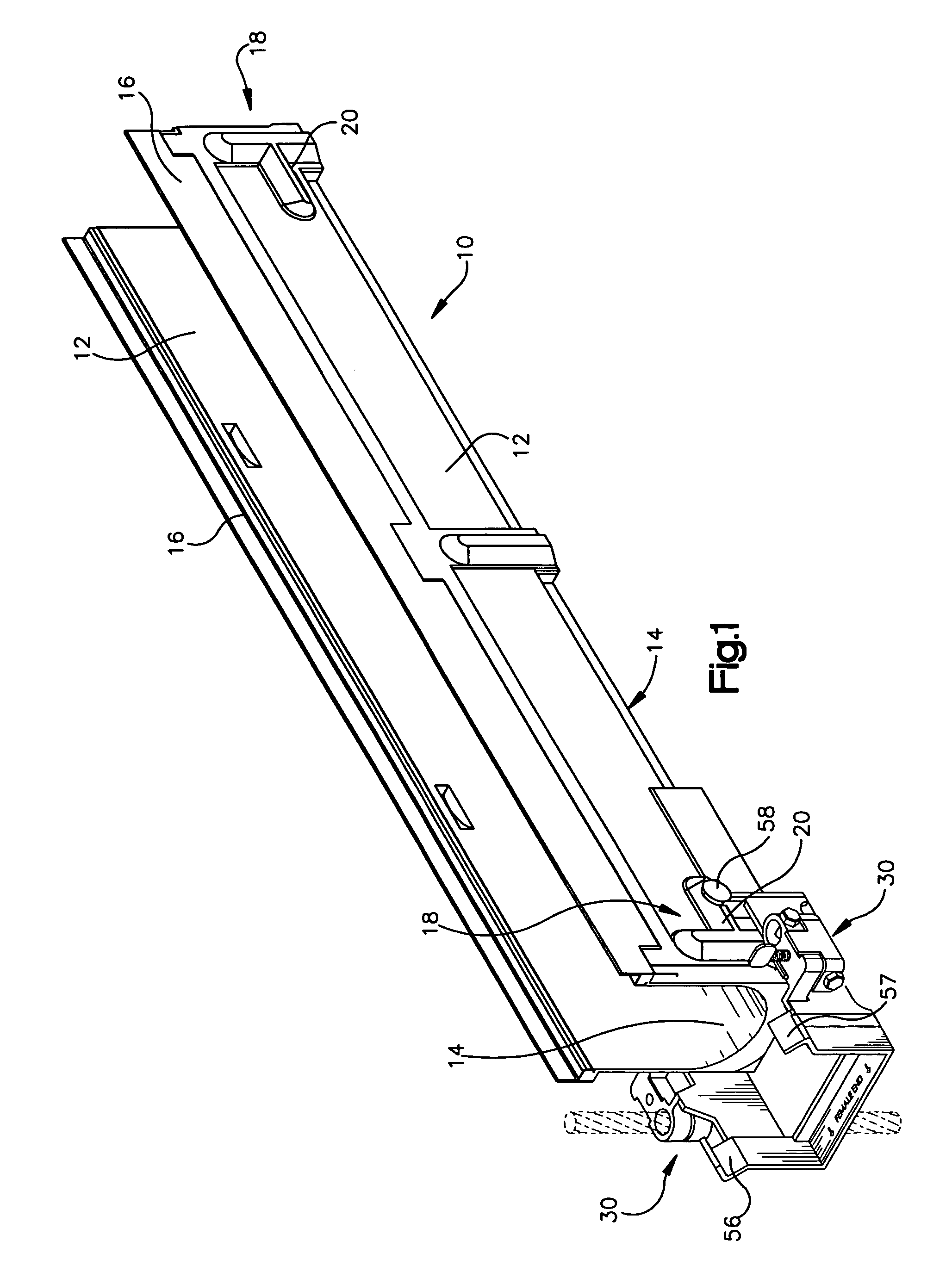
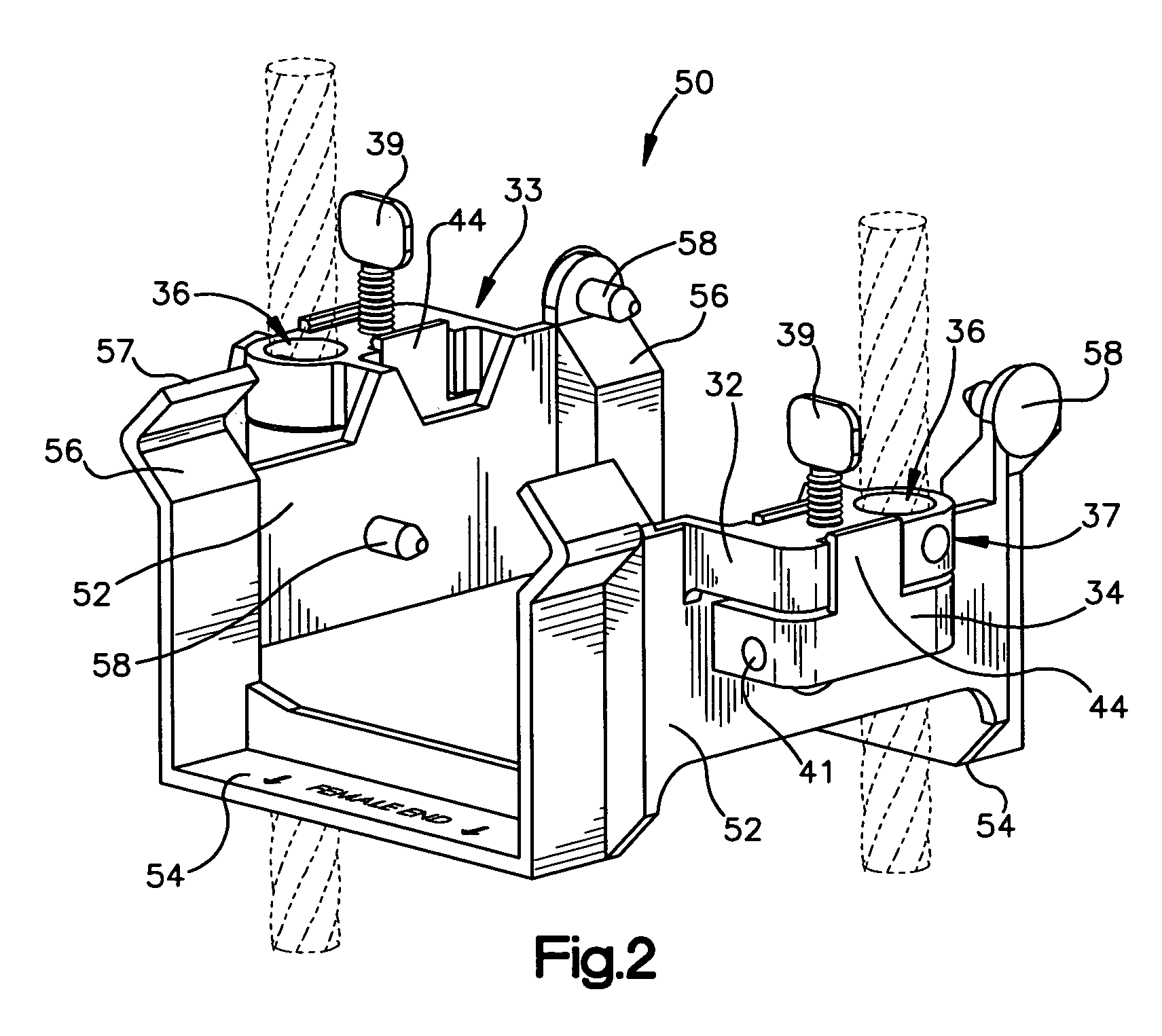
[0013]The present invention provides a drainage channel installation device and method which enables the efficient and accurate installation of drainage channels within a trench. A significant advantage of the installation device of the invention is that final channel alignment can be performed quickly, easily and precisely by a single worker. Thus, in accordance with the present invention there is provided an installation device in the form of a cradle assembly for supporting at least a portion of a drainage channel section or unit in an adjustable manner on a support member such as, for example, a steel reinforcing bar or rebar. The cradle is configured to receive a portion of at least one channel segment. Although the cradle can be configured to support the channel segment anywhere along its length, in preferred embodiments it is advantageous for the cradle to be configured to receive the respective male and female ends of two adjacent channel sections. Employing a cradle assembl...


PUM


Abstract

A cradle assembly for installing trench drain or conduit channels which enables the channels to be suspended from support rods while simultaneously permitting the adjustment of the channel height with in the trench. Because the assembly enables the channel to be supported by the support rods while permitting adjustment of the channel height, final adjustments can be performed by a single worker.

Description

RELATED APPLICATIONS[0001]This regular application claims the benefit of co-pending provisional application 60 / 587,567, filed Jul. 13, 2004 entitled “Drainage Channel Installation Device.”BACKGROUND OF THE INVENTION[0002]The present invention relates to trench drains or drainage channels used for the drainage of surface water or as ducting for cables and the like. Trench drains and similar drainage structures are used in a variety of environments, such as walkways, bike and foot paths, outdoor malls, parking lots, factories, airport tarmacs and other traffic environments which require the drainage of surface water or other fluids. Trench drains and drainage structures generally are known in the art as described in, for example, U.S. Pat. Nos. 4,630,966; 4,699,544; 5,462,382 and 4,553,874, incorporated herein by reference, and typically include a series of generally U-shaped channel segments or units aligned end-to-end along an excavated trench, and fixed in place by concrete or the ...

Claims


Application Information

Patent Timeline
Patent Type & Authority Patents(United States)
IPC IPC(8): E02B3/08E01C11/22
CPCE01C11/227H02G3/0608H02G3/263
Inventor HUMPHRIES, DEREKMCCONNELL, JAMES
Owner ACO POLYMER PRODS
Learn More