
Hollow Shaft Permanent Magnet Traction Motor Stator and Rotor Assembly Method and Device

A traction motor and hollow shaft technology, which is used in electromechanical devices, centering/balancing rotors, manufacturing motor generators, etc. Effect

Active Publication Date: 2022-06-21
CSR ZHUZHOU ELECTRIC CO LTD
View PDF13 Cites 0 Cited by
  • Summary
  • Abstract
  • Description
  • Claims
  • Application Information

AI Technical Summary

Problems solved by technology

[0002] The rotating shaft of the conventional permanent magnet traction motor is solid, and the two ends of the rotating shaft are processed with the process screw holes required for the assembly of the stator and the rotor to install the positioning and guiding tooling to ensure the accuracy of the assembly of the stator and the rotor to avoid the mutual attraction of the stator and the rotor to scratch the stator and the coil , The wheelside hollow shaft permanent magnet traction motor adopts the wheelside hollow rotor structure, and the driving end of the hollow rotor is directly connected to the wheel shaft to drive a single wheel. This special structure of the shaft is larger in size and lighter in weight than the solid shaft. The outer diameter of the rotor in this structure is larger It is easy to realize multi-pole direct drive. It is more commonly used in wheel-side low-floor trams. Since this kind of shaft does not have a process screw hole that can be directly used for the combination of stator and rotor, the existing permanent magnet traction motor stator and rotor combination device And the process can not meet the design requirements

Method used


Image

  • Hollow Shaft Permanent Magnet Traction Motor Stator and Rotor Assembly Method and Device
  • Hollow Shaft Permanent Magnet Traction Motor Stator and Rotor Assembly Method and Device
  • Hollow Shaft Permanent Magnet Traction Motor Stator and Rotor Assembly Method and Device

Examples


Embodiment Construction

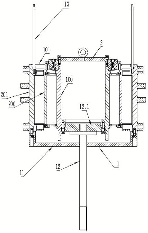
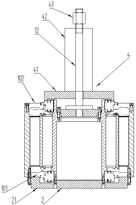
[0029] Combine below Figure 1 to Figure 4 The embodiments of the present invention will be described in detail.

[0030]The method for assembling the stator and the rotor of the permanent magnet traction motor with a hollow shaft at the wheel side is characterized in that firstly, the assembly of the non-transmission end bearing and the non-transmission end end cover 101 is press-fitted to the non-transmission end of the rotor 100 by means of shrink fit. On the corresponding bearing gear; then install the guide assembly 1 for combined guide on the rotor 100 and the stator 200 with the frame 201, and then combine the rotor 100 with the transmission end downward into the stator 200 by lifting and lowering, And in the process of assembly, use the guide assembly 1 to guide until the assembly is in place; then use the connecting assembly 2 to connect the non-transmission end of the rotor 100 and the stator 200 into one, and then turn 180 degrees to adjust the transmission end of t...


PUM


Abstract

The method and device for assembling the stator and rotor of the permanent magnet traction motor with a hollow shaft around the wheel. Firstly, the assembly of the non-drive end bearing and the non-drive end cover is press-fitted to the corresponding bearing gear of the non-drive end of the rotor by means of shrink fit. Afterwards, install the guide assembly for combined guidance on the rotor and the stator with the machine base, and then assemble the rotor with the drive end downward into the stator by hoisting and lowering, and use the guide assembly during the assembly process. Guide until it fits in place; then connect the rotor and the non-drive end of the stator as a whole with a connecting component, and then turn 180 degrees to adjust the drive end of the rotor and stator upward; then use a press-fit component to connect the drive end bearing with the drive The assembly of the end cover is press-fitted to the corresponding bearing block of the drive end of the rotor, and finally the non-drive end cover and the drive end cover are respectively fastened to the stator base of the stator with bolts. The invention improves the combined assembly efficiency while ensuring the safety and no damage of the stator, the rotor and the accessory parts.

Description

technical field [0001] The invention relates to a method and a device for assembling a stator and a rotor of a permanent magnet traction motor on a wheel-side hollow shaft. Background technique [0002] The shaft of the conventional permanent magnet traction motor is solid, and the two ends of the shaft are machined with process screw holes required for the combination of the stator and the rotor to install the positioning and guide tooling to ensure the accuracy of the combination of the stator and the rotor to prevent the stator and the rotor from attracting and scratching the stator and coil. , The wheel-side hollow shaft permanent magnet traction motor adopts the wheel-side hollow rotor structure, and the driving end of the hollow rotor directly connects to the wheel shaft to drive a single wheel. This special structure shaft is large in size and light in weight. The structural strength is better than the solid shaft. It is easy to realize multi-pole direct drive. It is ...

Claims


Application Information

Patent Timeline
Patent Type & Authority Patents(China)
IPC IPC(8): H02K15/16H02K15/14
CPCH02K15/16H02K15/14
Inventor 夏红勇王梓林杨下沙郭磊刘权兰万玲郑宇华龙云峰
Owner CSR ZHUZHOU ELECTRIC CO LTD
Learn More