Methods and apparatus for reducing crosstalk in electrical connectors

a technology of electrical connectors and crosstalk, applied in the field of modular communication connectors, can solve the problems of difficult to achieve the tuning effect achievable by the capacitors, the crosstalk generated within the connector increases dramatically,

Active Publication Date: 2007-08-07
PANDUIT
View PDF72 Cites 113 Cited by
  • Summary
  • Abstract
  • Description
  • Claims
  • Application Information

AI Technical Summary

Problems solved by technology

However, when such connectors are used to transmit high-frequency data signals, crosstalk generated within the connector increases dramatically.
However, due to the high level of crosstalk occurring in the plug for this connector at very high-frequency signal rates, the tuning effect achievable by the capacitors can still be difficult to accomplish.

Method used


Image

  • Methods and apparatus for reducing crosstalk in electrical connectors
  • Methods and apparatus for reducing crosstalk in electrical connectors
  • Methods and apparatus for reducing crosstalk in electrical connectors

Examples


Embodiment Construction

[0070]The present invention is directed to methods and apparatus for reducing crosstalk in electrical connectors. The present invention utilizes crosstalk-reduction principles of U.S. Pat. No. 5,997,358 to Adriaenssens et al., which is incorporated herein by reference in its entirety. The present application further incorporates by reference in its entirety commonly-assigned U.S. Provisional Patent Application No. 60 / 544,050 entitled “Methods and Apparatus for Reducing Crosstalk in Electrical Connectors,” filed Feb. 12, 2004, and commonly-assigned U.S. patent application Ser. No. 11 / 055,344, entitled “Methods and Apparatus for Reducing Crosstalk in Electrical Connectors,” filed Feb. 10, 2005.

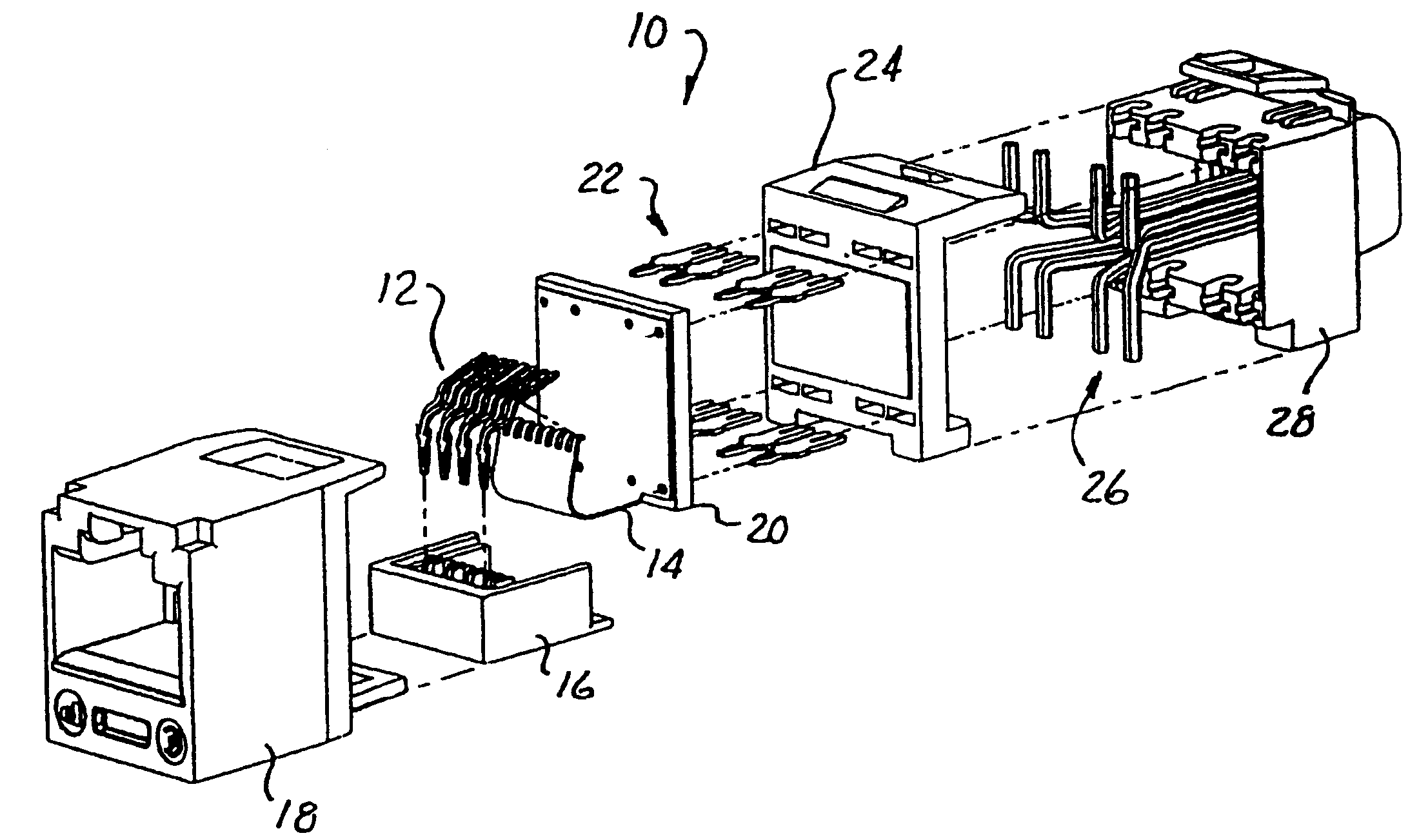
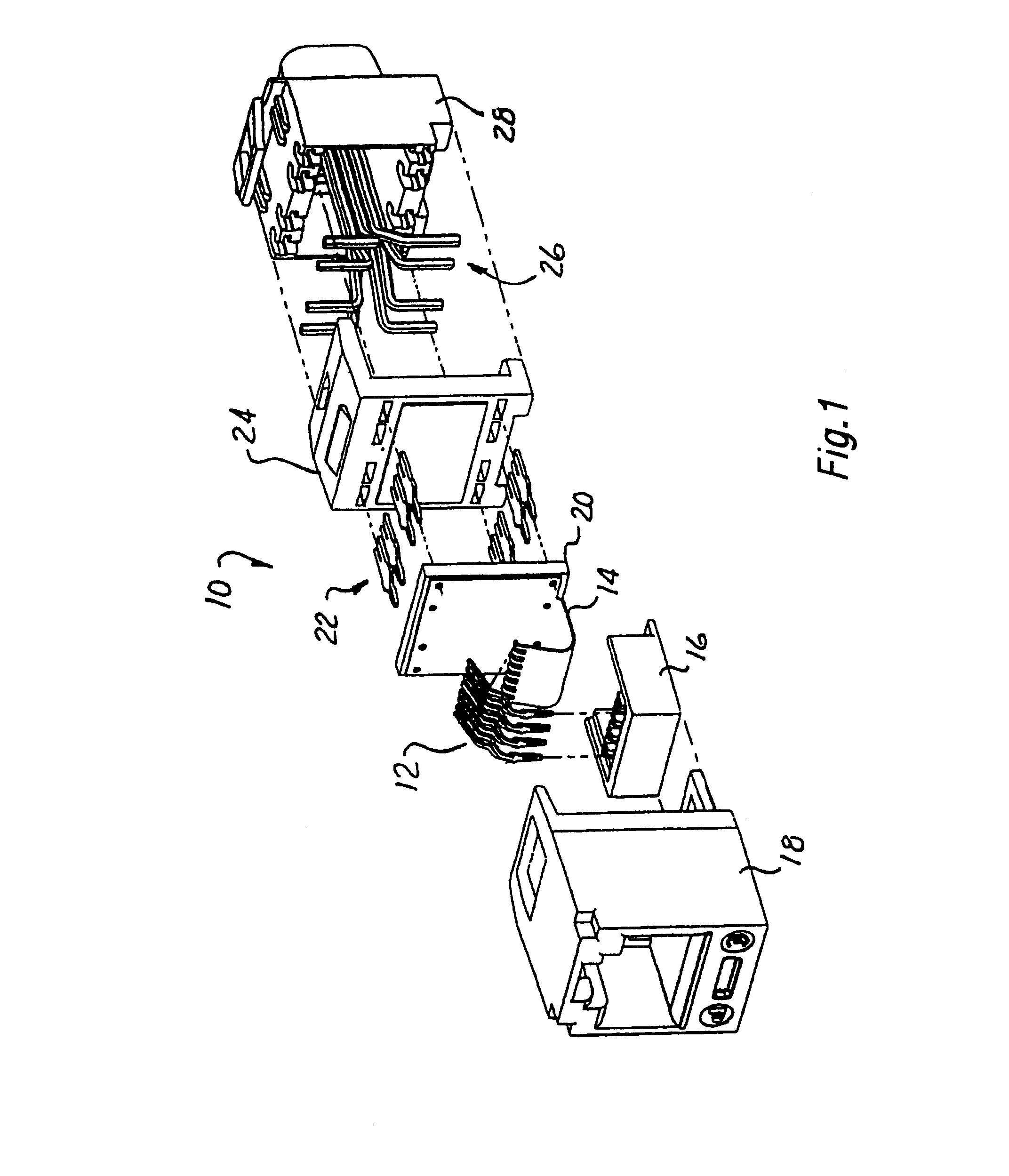
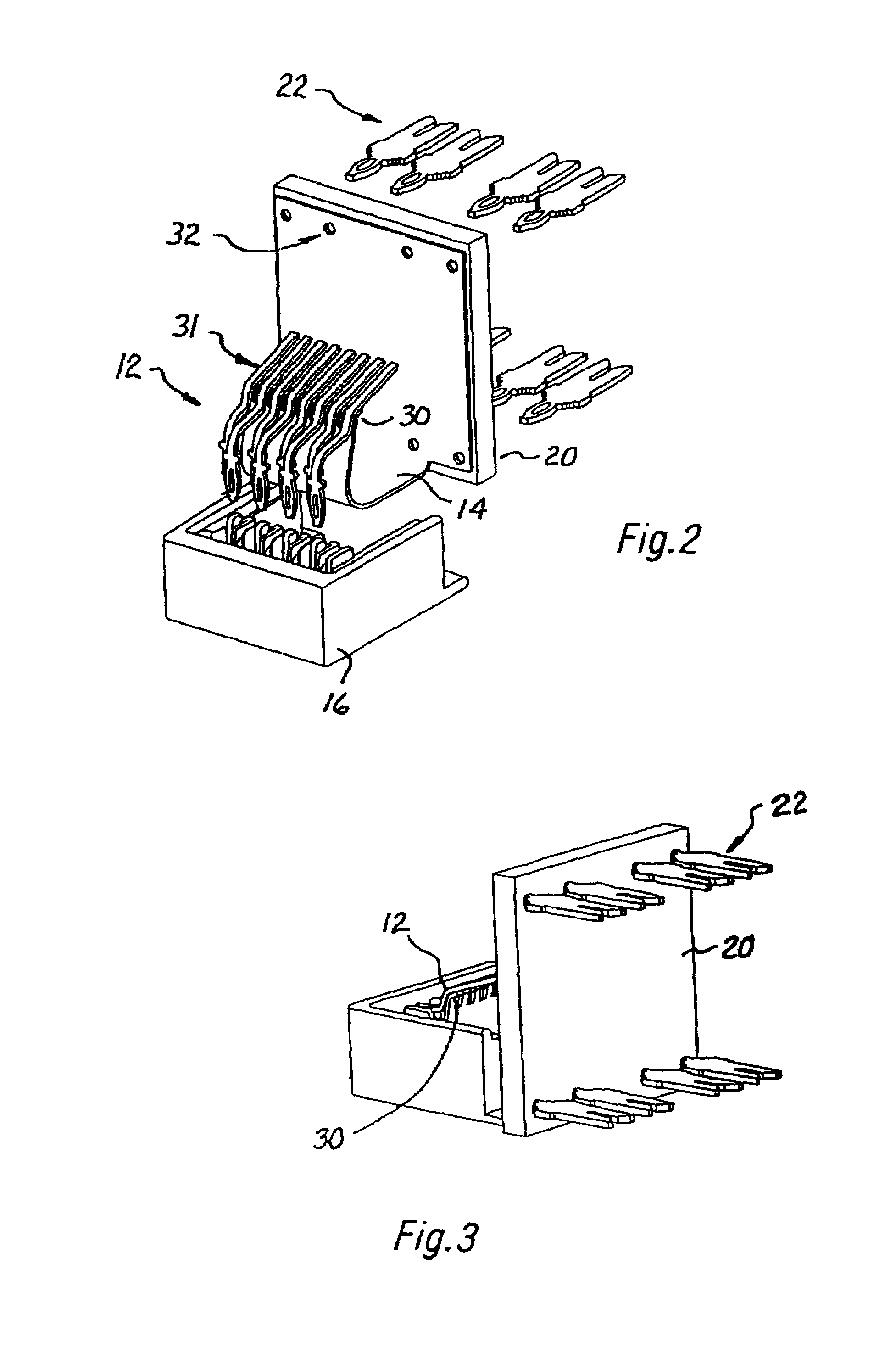
[0071]Turning now to FIG. 1, an exploded view of an electrical jack 10 is shown. Contacts 12 are adapted to make physical and electrical contact with contacts of a plug (not shown in FIG. 1) and further to make electrical contact with a flexible printed circuit (FPC) 14. The contacts 12 are mech...


PUM

PropertyMeasurementUnit
flexibleaaaaaaaaaa
frequencyaaaaaaaaaa
phase angleaaaaaaaaaa

Abstract

An apparatus and method for crosstalk compensation in a jack of a modular communications connector includes a flexible printed circuit board connected to jack contacts and to connections to a network cable. The flexible printed circuit board includes conductive traces arranged as one or more couplings to provide crosstalk compensation.

Description

CROSS-REFERENCE TO RELATED APPLICATIONS [0001]This application claims the benefit of U.S. Provisional Application No. 60 / 558,657, filed Apr. 1, 2004; and U.S. Provisional Application No. 60 / 552,995, filed Mar. 12, 2004, which are incorporated herein by reference in their entireties.TECHNICAL FIELD [0002]The present invention relates to electrical connectors and more particularly relates to modular communication connectors that utilize compensation techniques to reduce net crosstalk generated by the combination of a plug and a jack of a connector assembly.BACKGROUND[0003]Computer networks, including local area networks (LANs) and wide area networks (WANs), are becoming increasingly prevalent as the number of computers and network devices in the workplace grows. These computer networks utilize data communication cables and electrical connectors to transmit information between various components attached to the network. The electrical connectors are typically configured to include a pl...

Claims


Application Information

Patent Timeline
Patent Type & Authority Patents(United States)
IPC IPC(8): H01R24/00H01R12/00H01R13/66H01R24/58H05K1/02H05K1/18
CPCH05K1/0228H01R12/675H01R13/719H01R13/6466H01R12/775H01R13/46H01R13/6461H01R4/2433Y10T29/49222H01R12/62H01R13/6658H01R2201/04H05K1/189H05K2201/09245H05K2201/10189Y10S439/941H01R13/6467H01R24/64H01R4/2429Y10T29/49147Y10T29/49174Y10T29/49128Y10T29/49121H01R12/592H01R13/502H01R24/62H01R2107/00H05K1/028
Inventor CAVENEY, JACK E.BOLOURI-SARANSAR, MASUDLESNIAK, SCOTT M.
Owner PANDUIT
Why Eureka
Try Eureka