Proximity detector having a sequential flow state machine

a flow state machine and proximity detector technology, applied in the field of proximity detectors, can solve the problems of affecting the operation of the system, proximity detectors primarily tend to experience rotational vibration, and adverse to system operation

Active Publication Date: 2007-08-07
ALLEGRO MICROSYSTEMS INC
View PDF49 Cites 65 Cited by
  • Summary
  • Abstract
  • Description
  • Claims
  • Application Information

AI Technical Summary

Problems solved by technology

For example, when used in an automobile transmission, during starting of the automobile engine, the proximity detector primarily tends to experience rotational vibration, which tends to generate magnetic field signals having a first wave shape.
In contrast, during engine idle, the proximity detector primarily tends to experience translational vibration, which tends to generate magnetic field signals having a second wave shape.
It may be adverse to the operation of a system, for example, an automobile system in which the proximity detector is used, for the system to interpret an output signal from the proximity detector to be associated with a rotation in normal operation when only a vibration is present.
Therefore, the antilock brake system might not operate as intended.
It may also be undesirable to perform the above-described proximity detector calibration in response to a vibration rather than in response to a rotation in normal operation.
Since the conventional proximity detector cannot distinguish a magnetic field signal generated in response to a rotation in normal operation from a magnetic field signal generated in response to a vibration, the proximity detector may perform calibrations at undesirable times when experiencing the vibration, and therefore, result in inaccurate calibration.

Method used


Image

  • Proximity detector having a sequential flow state machine
  • Proximity detector having a sequential flow state machine
  • Proximity detector having a sequential flow state machine

Examples


Embodiment Construction

[0033]Before describing the present invention, some introductory concepts and terminology are explained. As used herein, the term “rotational vibration” refers to a back and forth rotation of an object about an axis of rotation, which object is adapted to rotate in a unidirectional manner about the axis of rotation in normal operation. As used herein, the term “translational vibration” refers to translation of the object and / or of magnetic field sensors used to detect magnetic fields generated by the object generally in a direction perpendicular to the axis of rotation. It should be recognized that both rotational vibration and translational vibration can cause signals to be generated by the magnetic field sensors.

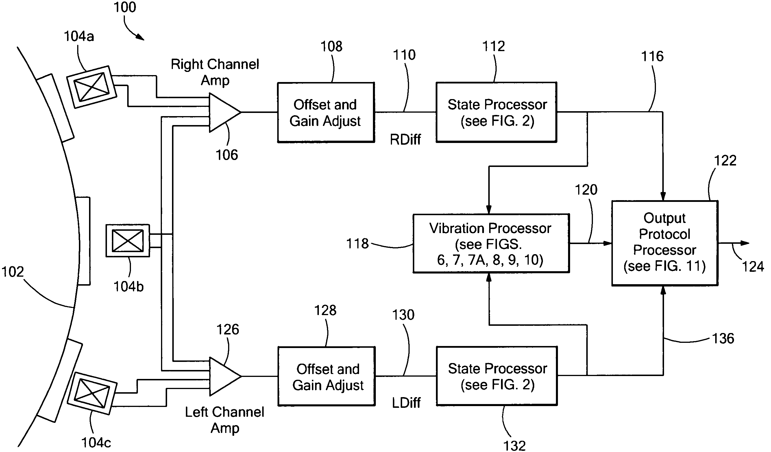
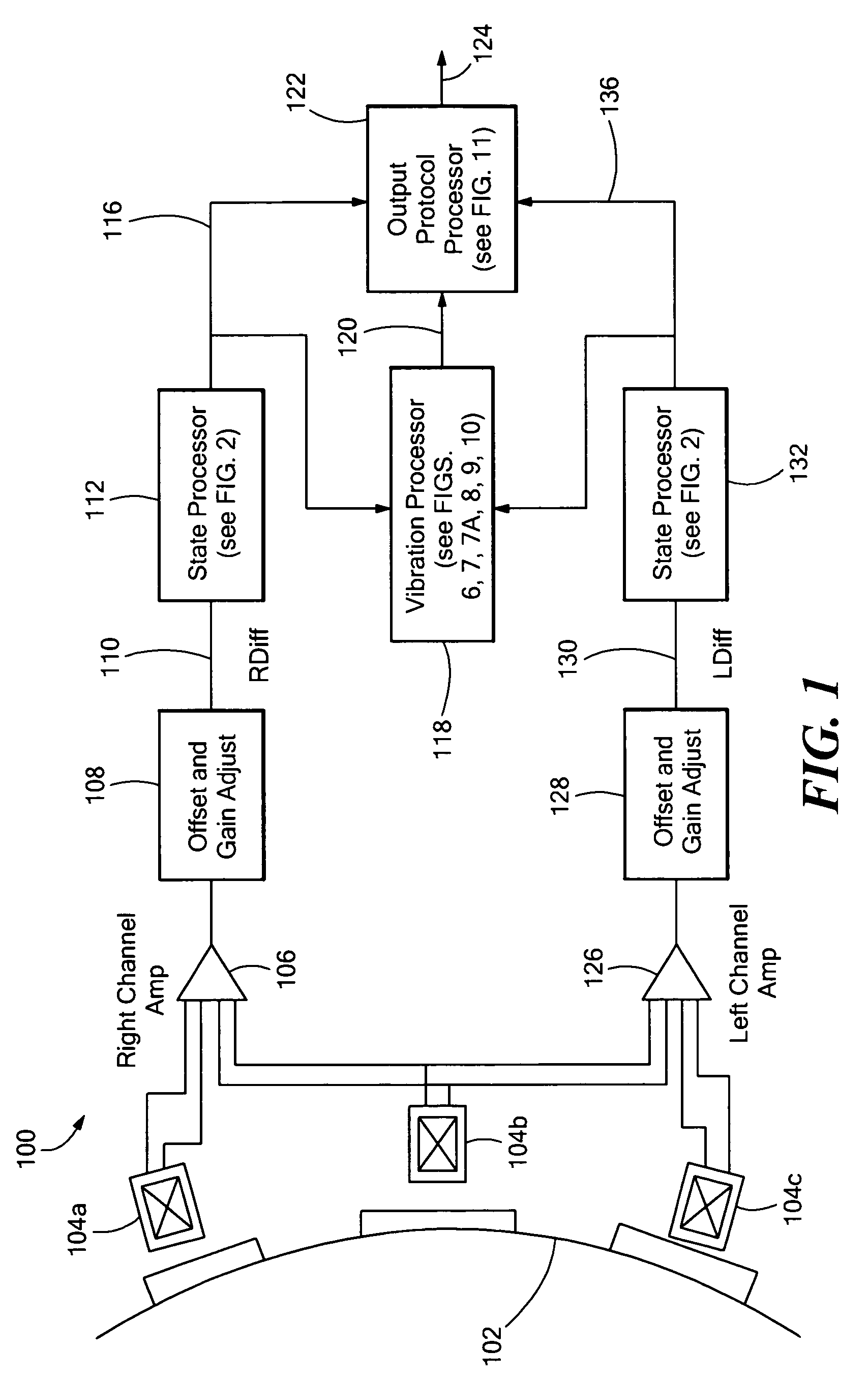
[0034]Referring to FIG. 1, an exemplary proximity detector system 100, includes three magnetic field sensing elements 104a-104c, each adapted to generate a respective magnetic-field-sensing-element signal in response to passing teeth of a rotating gear 102. The system 100 ...


PUM


Abstract

A proximity detector has a sequential flow state machine to identify states associated with a magnetic field signal provided by a magnetic field sensing element. The proximity detector can include a vibration processor to identify a vibration in response to the states.

Description

CROSS REFERENCE TO RELATED APPLICATIONS[0001]Not Applicable.STATEMENT REGARDING FEDERALLY SPONSORED RESEARCH[0002]Not Applicable.FIELD OF THE INVENTION[0003]This invention relates to proximity detectors, and more particularly, to a proximity detector that has a sequential flow state machine.BACKGROUND OF THE INVENTION[0004]Proximity detectors (also referred to herein as rotation detectors) for detecting ferrous or magnetic objects are known. One application for such devices is in detecting the approach and retreat of each tooth of a rotating ferrous object, such as a ferrous gear. The magnetic field associated with the ferrous object is often detected by one or more magnetic field-to-voltage transducers (also referred to herein as magnetic field sensing elements), such as Hall elements or magnetoresistive devices, which provide a signal proportional to a detected magnetic field (i.e., a magnetic field signal). The proximity detector processes the magnetic field signal to generate an...

Claims


Application Information

Patent Timeline
Patent Type & Authority Patents(United States)
IPC IPC(8): G01B7/14
CPCG01D5/2448G01D5/2449G01D5/2451
Inventor FORREST, GLENN A.BAILEY, JAMES M.LAMAR, WASHINGTON
Owner ALLEGRO MICROSYSTEMS INC
Why Eureka
Try Eureka