Outside structure conformal antenna in a supporting structure of a vehicle

a technology of conformal antenna and supporting structure, which is applied in the direction of antenna adaptation in movable bodies, radiating element structural forms, electrical devices, etc., can solve the problems of increasing the cost of installation, so as to maintain the structural strength in the integration area

Active Publication Date: 2007-08-07
AIRBUS DEFENCE & SPACE
View PDF13 Cites 23 Cited by
  • Summary
  • Abstract
  • Description
  • Claims
  • Application Information

AI Technical Summary

Benefits of technology

[0015]An aspect of the invention is to integrate outside structure conformal antennae into the supporting structures and in particular into supporting system primary structures of vehicles and / or aircraft in such a way that any aerodynamic disadvantages are avoided, and the structural strength in the integration areas is maintained to the greatest possible extent, while simultaneously safeguarding the antenna functionality.
[0020]As compared to conventional antenna constructions, the invention thus offers significant weight and volume savings, which have a particularly advantageous effect in airplanes. Aerodynamic disadvantages are reduced with use of the invention, since the shape of the outer shell of the structures remains completely unchanged. By now, practical examinations have shown that the structural strength is affected by the invention at the most to a negligibly small extent.
[0021]Furthermore, structurally integrated antennae according to the invention offer, particularly in aircraft, the opportunity to be arranged in areas that so far have not been justifiable or have even been unsuitable for conventional antennae. Furthermore, the invention renders it possible to incorporate antennae into rudder or flap structures in airplanes or also into fuelled structures if appropriate precautions are taken with regard to the high-frequency lines.

Problems solved by technology

This problem requires new ways of mounting or housing antennae, e g., in airplanes.
Their housing, however, is usually a problem.
With the expansion of the function of the structural surface of aircraft to act also as an antenna, additional problems arise in terms of the stability of the structures.

Method used


Image

  • Outside structure conformal antenna in a supporting structure of a vehicle
  • Outside structure conformal antenna in a supporting structure of a vehicle
  • Outside structure conformal antenna in a supporting structure of a vehicle

Examples


Embodiment Construction

[0037]The particulars shown herein are by way of example and for purposes of illustrative discussion of the embodiments of the present invention only and are presented in the cause of providing what is believed to be the most useful and readily understood description of the principles and conceptual aspects of the present invention. In this regard, no attempt is made to show structural details of the present invention in more detail than is necessary for the fundamental understanding of the present invention, the description taken with the drawings making apparent to those skilled in the art how the several forms of the present invention may be embodied in practice.

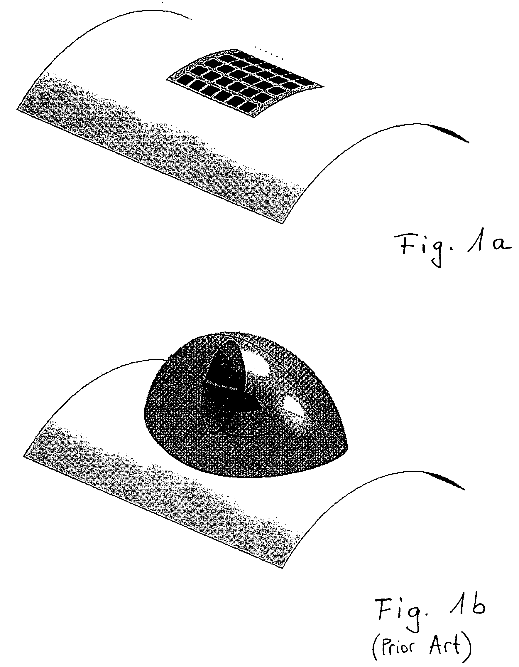
[0038]FIG. 1a graphically illustrates the advantages of an antenna according to the invention as compared to a conventional antenna according to FIG. 1b. FIG. 1a represents a completely outside structure conformal antenna subsystem, e.g., for a broadband data link in the microwave range. The integration of the antenna acc...


PUM


Abstract

An antenna mounted on a supporting system primary structure of a vehicle, in which the supporting system primary structure has an indentation. The antenna includes an EM functional core incorporated into the indentation of the supporting system primary structure, and a cover plate forming one of an upper and outer cover of the EM functional core that is structured and arranged as a conformal outside. Furthermore, boundary areas of the cover plate are connected with the supporting system primary structure. The instant abstract is neither intended to define the invention disclosed in this specification nor intended to limit the scope of the invention in any way.

Description

CROSS-REFERENCE TO RELATED APPLICATIONS[0001]The present application claims priority under 35 U.S.C. §119 of German Patent Application No. 103 56 395.6, filed on Dec. 3, 2003, the disclosure of which is expressly incorporated by reference herein in its entirety.BACKGROUND OF THE INVENTION[0002]1. Field of the Invention[0003]The invention relates to an outside structure conformal antenna and in particular, to a flat broadband antenna in a supporting structure of a vehicle and more specifically an aircraft, whereby the supporting structure is in particular a supporting system primary structure.[0004]2. Discussion of Background Information[0005]The term “aircraft” relates to all conceivable devices that can be propelled through the air by any drives, devices such as airplanes, helicopters, airships, drones, rockets, and the like. The example of rockets shows that the invention can also relate to aircraft or missiles that are suitable to fly both in the air and in space.[0006]The increa...

Claims


Application Information

Patent Timeline
Patent Type & Authority Patents(United States)
IPC IPC(8): H01Q1/32H01Q1/28
CPCH01Q1/286H01Q1/32
Inventor BLASCHKE, DETLEVBRAND, CLEMENSDITTRICH, KAYNAGY, OLIVERRITTER, JANSEKORA, ROBERTZIPPOLD, HERBERT
Owner AIRBUS DEFENCE & SPACE
Why Eureka
Try Eureka