Dielectric resonator antenna

a dielectric resonator and antenna technology, applied in slot antennas, antennas, electrical equipment, etc., can solve the problems of difficult mode excitation, high dielectric materials to be used, antennas being too small in bandwidth, etc., to achieve good azimuth coverage, good control of radiation pattern, and high gain

Inactive Publication Date: 2007-08-07
ANTENOVA LTD +1
View PDF14 Cites 36 Cited by
  • Summary
  • Abstract
  • Description
  • Claims
  • Application Information

AI Technical Summary

Benefits of technology

[0013]An improved DRA and a method of efficiently slot feeding the EH11δ mode in a half-split cylindrical DRA has been found by the present applicants and is presented in this patent application. This method may also apply to DRAs having dielectric resonators with shapes other than half-split cylindrical.
[0045]A further advantage of the array is that a vertical monopole-type antenna can be constructed that is nearly omnidirectional, but which has higher gain than can be obtained using dipoles. A typical vertical electric dipole may have a peak element gain of about 2 dBi and array of five such dipoles, for example, would have a total peak gain of about 9 dBi. The DRA elements of embodiments of the present invention have been found to have gains of up to 4 dBi (even higher gains may potentially be achieved), and thus an array of these elements will have a total peak gain of about 11 dBi while still retaining the good azimuth coverage of the dipoles. It is possible that further development of the DRA elements may lead to even further gain improvements in future.

Problems solved by technology

A problem with designing miniature dielectric resonator antennas for portable communications systems (e.g. mobile telephone handsets and the like) is that high dielectric materials must be used to make the antennas small enough to be physically compatible with the portable communications system.
This in turn often leads to the antenna being too small in bandwidth.
Unfortunately, although it has been reported in the academic press that the EH11δ is a possible mode of a half-split cylindrical DRA [MONGIA R. K., et. al
Indeed, it is a difficult mode to excite, because the plane of symmetry is required to be magnetic rather than electric and so a simple conducting substrate or groundplane containing a probe or slot or similar feed structure cannot be used.

Method used


Image

  • Dielectric resonator antenna
  • Dielectric resonator antenna
  • Dielectric resonator antenna

Examples


Embodiment Construction

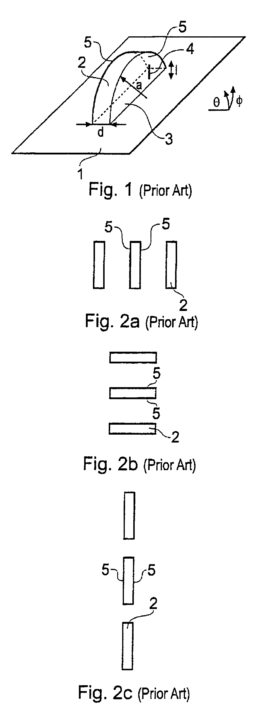
[0059]FIGS. 1, 2a, 2b and 2c have been discussed in the introduction to the present application.

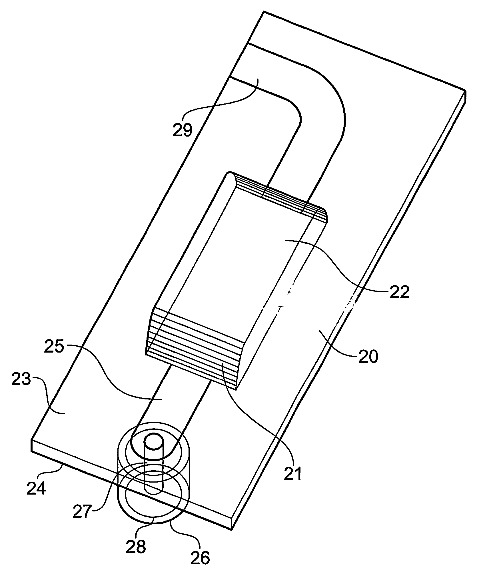
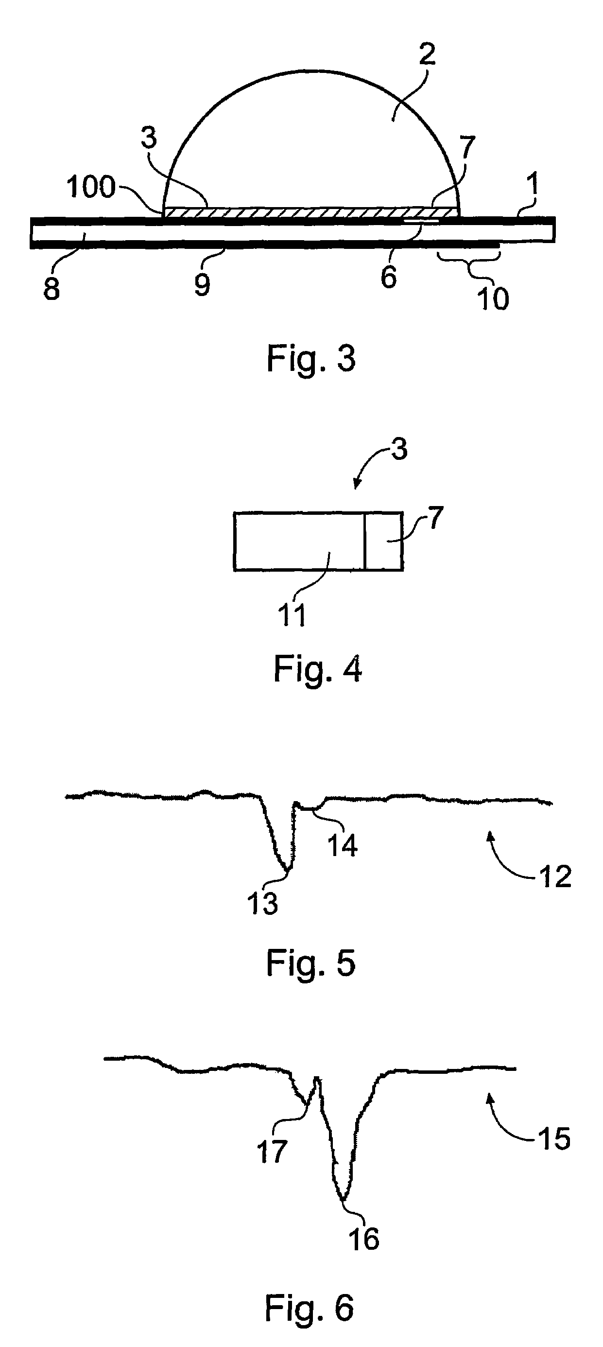
[0060]FIG. 3 shows a preferred DRA of the present invention comprising a grounded conductive substrate 1 over which is disposed a half-split cylindrical ceramic dielectric resonator 2 having a longitudinal rectangular surface 3 disposed just over the grounded substrate 1. The grounded dielectric substrate 1 includes a slot 6 formed therein, the slot 6 extending longitudinally in a direction substantially perpendicular to the orientation of the longitudinal surface 3 of the resonator 2, with one end 7 of the longitudinal surface 3 positioned over the slot 6. The grounded substrate 1 is disposed on a first side of a dielectric substrate 8, which may be a printed circuit board (PCB). A microstrip feed line 9 is provided on a second side of the dielectric substrate 8, the feed line 9 being substantially coextensive with the longitudinal surface 3 of the resonator 2 and extending slightly beyo...


PUM


Abstract

There is disclosed a dielectric resonator antenna adapted to resonate in an EH11δ resonance mode, and also a method for the manufacture thereof. The desired resonance mode is achieved by careful positioning of a dielectric resonator (2) on a grounded substrate (1), the resonator (2) being fed by way of a microstrip feed line (9) and a slot (6) in the grounded substrate (1). Because the EH11δ resonance mode has nulls in a direction of longitudinal extension of the dielectric resonator (2), a plurality of antenna can be placed end-to-end so as to form an array with reduced coupling between adjacent antennas and with vertical polarisation, which is desirable for mobile communications applications.

Description

PRIOR APPLICATION DATA[0001]The present application is a national phase application of International Application PCT / GB03 / 01326, entitled “DIELECTRIC RESONATOR ANTENNA” filed on Mar. 26, 2003, which in turn claims priority from United Kingdom application 0207052.2, filed on Mar. 26, 2002, both of which are incorporated by reference in their entirety.FIELD OF THE INVENTION[0002]The present invention relates to a dielectric resonator antenna (DRA) configured so as to be capable of operating in modes such as EH11δ, TE02δ, TE02, TE01 and hybrid modes, and also to arrays of such DRAs in which the patterns of the individual DRA elements are configured so as to endow the overall array pattern with special properties designed to meet the requirements of certain applications.BACKGROUND OF THE INVENTIONIntroduction to DRAs[0003]Dielectric resonator antennas are resonant antenna devices that radiate or receive radio waves at a chosen frequency of transmission and reception, as used for example...

Claims


Application Information

Patent Timeline
Patent Type & Authority Patents(United States)
IPC IPC(8): H01Q15/08H01Q9/04H01Q13/00H01Q13/08H01Q13/10H01Q21/08
CPCH01Q9/0485H01Q21/08H01Q9/04
Inventor KINGSLEY, SIMON PHILIPO'KEEFE, STEVEN GREGORYPALMER, TIM JOHNKINGSLEY, JAMES WILLIAM
Owner ANTENOVA LTD
Why Eureka
Try Eureka