Non-destructive inspection using laser profiling and associated method

a technology of laser profiling and workpieces, applied in the field of non-destructive inspection, can solve the problems of prone to human error, lack of useful output for analysis, time-consuming feeler gauge inspection, etc., and achieve the effect of reducing downtime and operational and maintenance costs and being advantageously portabl

Active Publication Date: 2007-08-07
THE BOEING CO
View PDF21 Cites 36 Cited by
  • Summary
  • Abstract
  • Description
  • Claims
  • Application Information

AI Technical Summary

Benefits of technology

[0014]The present invention therefore provides an inspection system that is capable of providing accurate and reliable images of a workpiece inspected. The inspection system is also efficient, which reduces downtime and operational and maintenance costs. The inspection system incorporates a laser and camera that dynamically generate data indicative of the surface profile of the workpiece inspected. The data generated by the camera and laser is capable of being used to create C-scan and B-scan images that are useful in analyzing the workpiece inspected. The inspection system is advantageously portable so that it may be used in a variety of locations and even remotely from a central inspection location.

Problems solved by technology

Inspecting with feeler gauges are time consuming, lack useful output for analysis, and are prone to human error.

Method used


Image

  • Non-destructive inspection using laser profiling and associated method
  • Non-destructive inspection using laser profiling and associated method
  • Non-destructive inspection using laser profiling and associated method

Examples


Embodiment Construction

[0020]The present invention now will be described more fully hereinafter with reference to the accompanying drawings, in which some, but not all embodiments of the invention are shown. Indeed, this invention may be embodied in many different forms and should not be construed as limited to the embodiments set forth herein; rather, these embodiments are provided so that this disclosure will satisfy applicable legal requirements. Like numbers refer to like elements throughout.

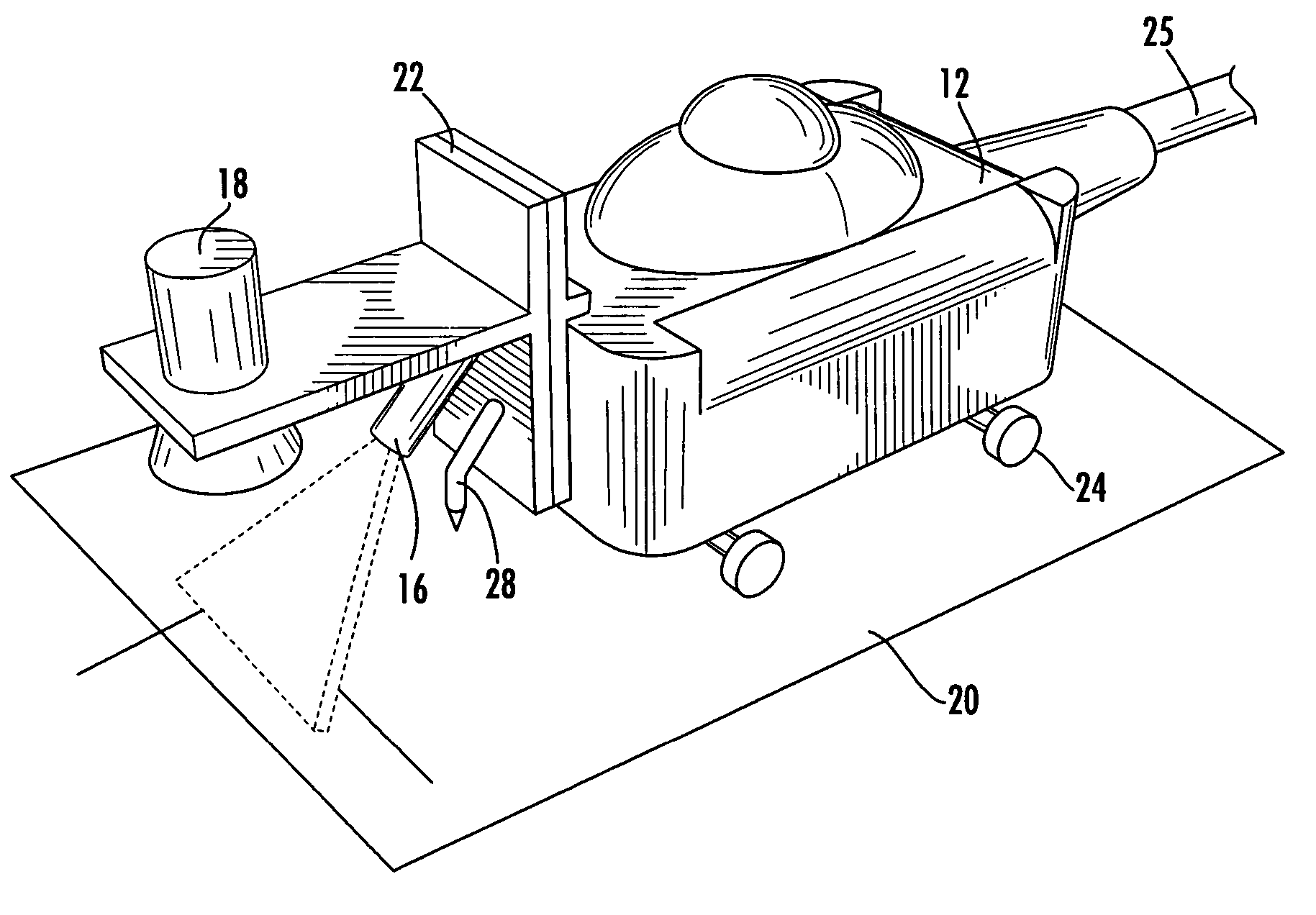
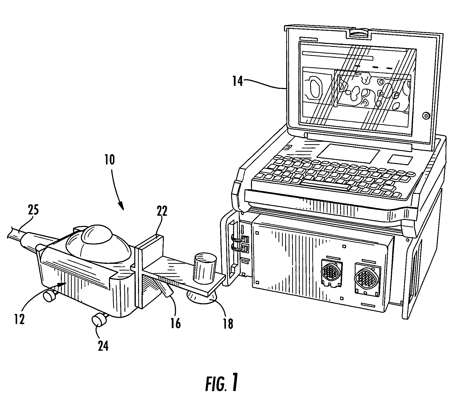
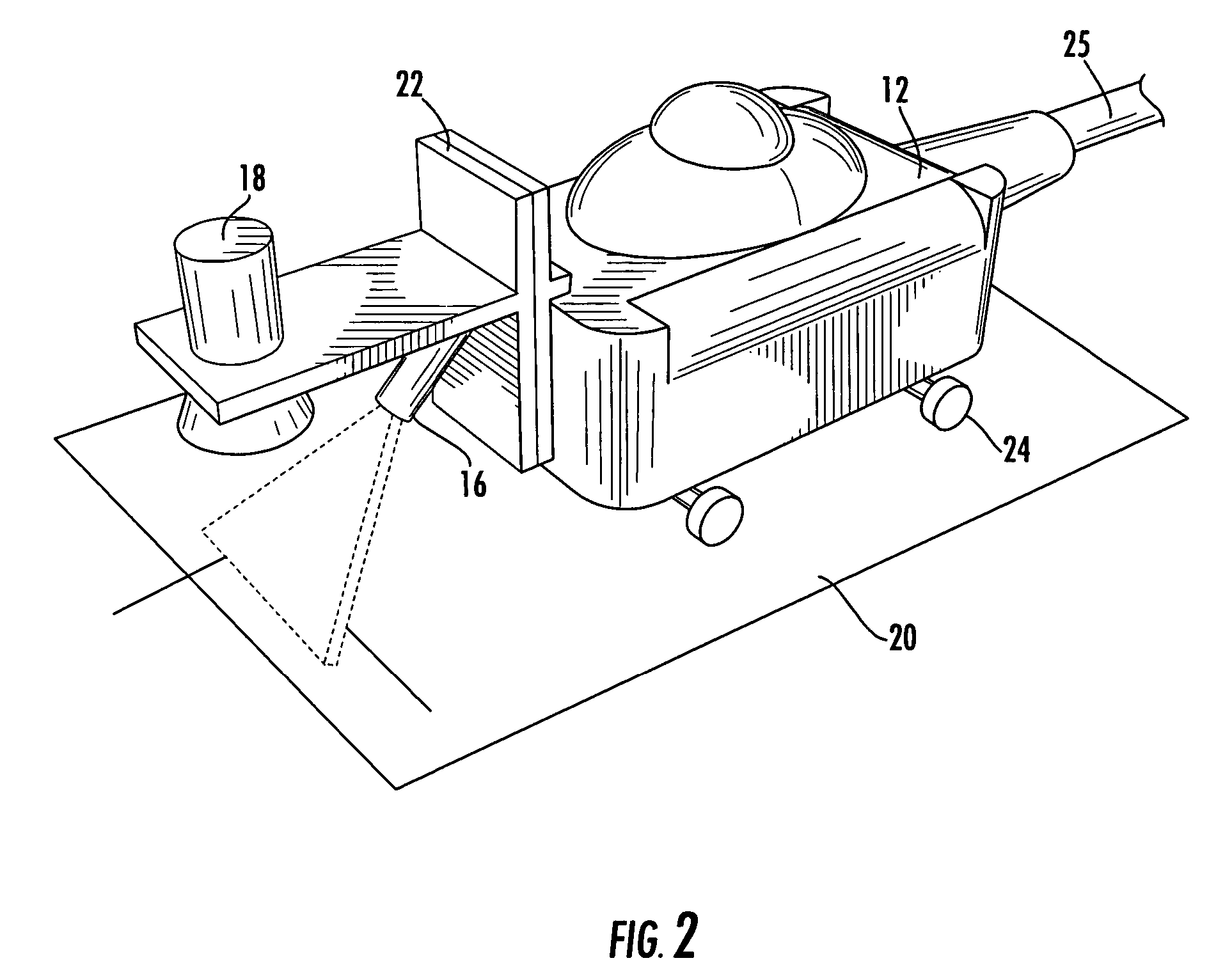
[0021]Referring now to the drawings and, in particular to FIGS. 1-2, there is shown an inspection system 10. The inspection system 10 includes a scan head 12 having a laser 16 and camera 18 coupled thereto, as well as a data acquisition system 14. As the laser 16 and camera 18 are moved along a workpiece 20, data is collected by the camera and communicated to the data acquisition system 14 for processing. Typically, as the scan head 12 moves the laser 16 proximate to the workpiece 20, the data acquisition system 1...


PUM


Abstract

A system for non-destructive inspection using laser profiling and an associated method are provided. The system includes a support surface, and at least one laser carried by the support surface and directed towards the workpiece at an oblique angle such that at least a portion of the workpiece is illuminated by the laser. The system also includes a camera carried by the support surface and capable of capturing reflections from the workpiece, as well as a translation device capable of traveling proximate to the workpiece. The support surface is coupled to the translation device such that the laser and the camera are capable of traveling along the workpiece. The system further includes a data acquisition system capable of communicating with the camera such that the data acquisition system creates an image indicative of at least a portion of the workpiece based on the reflections from the workpiece.

Description

BACKGROUND OF THE INVENTION[0001]1) Field of the Invention[0002]The present invention relates to non-destructive inspection and, more particularly, to non-destructive inspection of a workpiece using laser profiling, as well as an associated method.[0003]2) Description of Related Art[0004]Non-destructive testing of structures involves thoroughly examining a structure without harming, or requiring significant disassembly of, the structure. Non-destructive testing is advantageous for many applications in which a thorough inspection of the exterior and / or interior of a structure is required. For example, non-destructive testing is commonly utilized in the aircraft industry to inspect aircraft structures for any type of internal or external damage to the structure. Metallic aircraft structures are typically inspected for corrosion and / or cracking, particularly near fasteners in the structure. Composite structures are typically inspected for any type of damage, such as delamination, occur...

Claims


Application Information

Patent Timeline
Patent Type & Authority Patents(United States)
IPC IPC(8): G01B11/24G06K9/00
CPCG01B11/24G01N21/8806
Inventor VACCARO, CHRISTOPHER M.ENGELBART, ROGER W.WOOD, NANCY L.
Owner THE BOEING CO
Why Eureka
Try Eureka