
Conveyor belt rip detection system with microwire sensor

a detection system and conveyor belt technology, applied in conveyor parts, transportation and packaging, rubber insulators, etc., can solve the problems of high cost component of industrial material handling operation, rip, slit, cut or tear within the belt, etc., to increase the durability and service life of the rip detection system, improve the service life, and reduce maintenance costs and downtime.

Active Publication Date: 2016-09-27
CONTITECH USA INC
View PDF16 Cites 2 Cited by
  • Summary
  • Abstract
  • Description
  • Claims
  • Application Information

AI Technical Summary

Benefits of technology

[0011]The present invention relates to conveyor belts having rip detection systems which utilize microcoil sensor wires which offer improved durability as compared to conventional microcoil sensor wires, including microcoil springwires as described in U.S. Pat. No. 6,352,149. This is because the microcoil sensor wires utilized in the conveyor belt rip detection systems of this invention can be elongated to a higher degree without sustaining damage. This higher acceptable degree of elongation which can be experienced without causing damage increases the durability and service life of the rip detection system and allows for the conveyor belt to be used reliably over an extended time period without the need to replace damaged microcoil sensor wires within the rip detection system of the conveyor belt. This reduces maintenance costs and the downtime which would ordinarily be encountered for repairing rip detection systems damage relating to microcoil sensor wires therein. In any case, the conveyor belts of this invention have rip detection systems which offer extended service life, excellent reliability, and excellent durability during normal and unusual operating conditions.
[0012]The microcoil sensor wires employed in the conveyor belts of this invention have elongations to break of at least about 100%. Such microcoil sensor wires typically have an elongation to break within the range of 100% to 1000%. More typically, the microcoil sensor wires will have an elongation to break within the range of 200% to 500%. In many cases the microcoil sensor wires will have an elongation to break of at least 150% or 200%. In any case, the microcoil sensor wires have the ability to move relatively freely within the elastomeric body of the conveyor belt in cases the body of the conveyor belt is strained. This is in contrast to conventional wires which are more closely coupled with or bonded to the rubber of the elastomeric body of the conveyor belt with such conventional wires breaking when strains exceed the maximum elongation of the wire. However, the core material of the microcoil sensor wires employed in the conveyor belts of this invention have a higher elongation than the elastomeric material utilized in the body of the conveyor belt and the microsensor wires can stretch with the core increasing the amount of elongation that the microcoil sensor wire can achieve without incurring damage. The fact that it is not mechanically restricted by the elastomeric body of the conveyor belt through a mechanical means or by an adhesive or some other form of chemical bonding allows for more freedom to strain and not break or otherwise to incur damage during events that cause a high level of elongation. In other words, in cases where the microcoil sensor wire is insulated in a sheath it is not mechanically bound directly to the elastomeric body of the conveyor belt giving it a high degree of freedom of movement independent of the elastomeric body of the belt.

Problems solved by technology

Heavy duty conveyor belts used in mining operations can extend over distances of several miles and represent a high cost component of an industrial material handling operation.
Unfortunately, such conveyor belts are susceptible to damage from the material transported thereon and a rip, slit, cut or tear may develop within the belt.
For instance, sharp edges of the material being transported can gouge the surface of the belt and that can result in a rip developing.
However, the cost of repairing a heavy duty conveyor belt and cleaning up material spilled as a result of the damage can be substantial.
In cases where such damage is not detected and repaired promptly, the rip typically propagates along the length of the belt with continued use of the conveyor system which makes the repair even more difficult and costly.
The performance and reliability of microcoil springwires utilized in conveyor belt rip detection systems, such as the system disclosed by U.S. Pat. No. 6,352,149, can be compromised due to breaks, micro-breaks, or partial breaks therein which are caused by the microcoil springwire being elongated beyond its breaking point during the normal operation of the belt or as a result of belt damage.
In other words, the microcoil spring wire can be damaged during normal belt operations as a consequence of ordinary wear and tear or it can be damaged by a high level of strain which is encountered during a high elongation event which causes the belt to stretched beyond the levels encountered during normal operations.
In any case, the microcoil sensor wires utilized in the rip detection systems of conveyor belts can are susceptible to damage which is typically the result of being elongated beyond the break point of the microcoil sensor wire.
The presence of breaks, micro-breaks, or partial breaks in the microcoil springwire compromises its electrical properties and accordingly adversely affects the performance and reliability of the rip detection system.

Method used


Image

  • Conveyor belt rip detection system with microwire sensor
  • Conveyor belt rip detection system with microwire sensor
  • Conveyor belt rip detection system with microwire sensor

Examples


Embodiment Construction

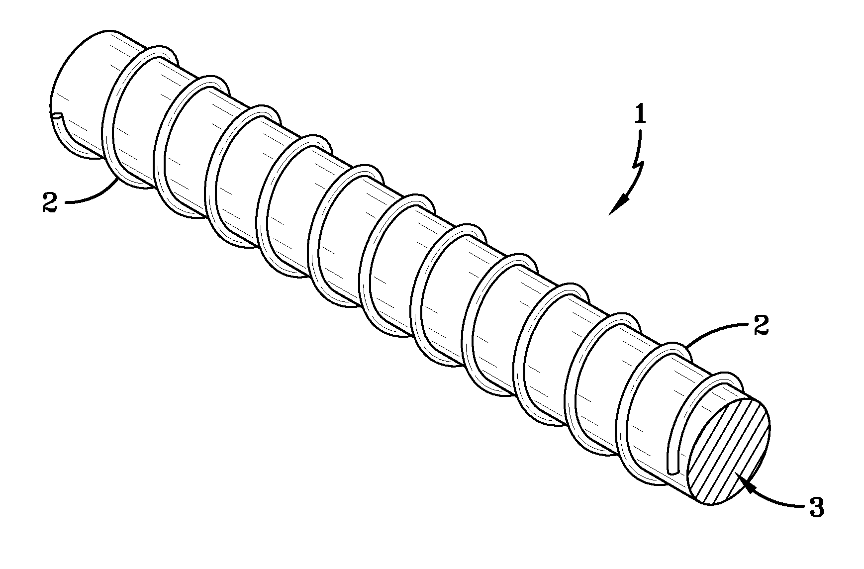
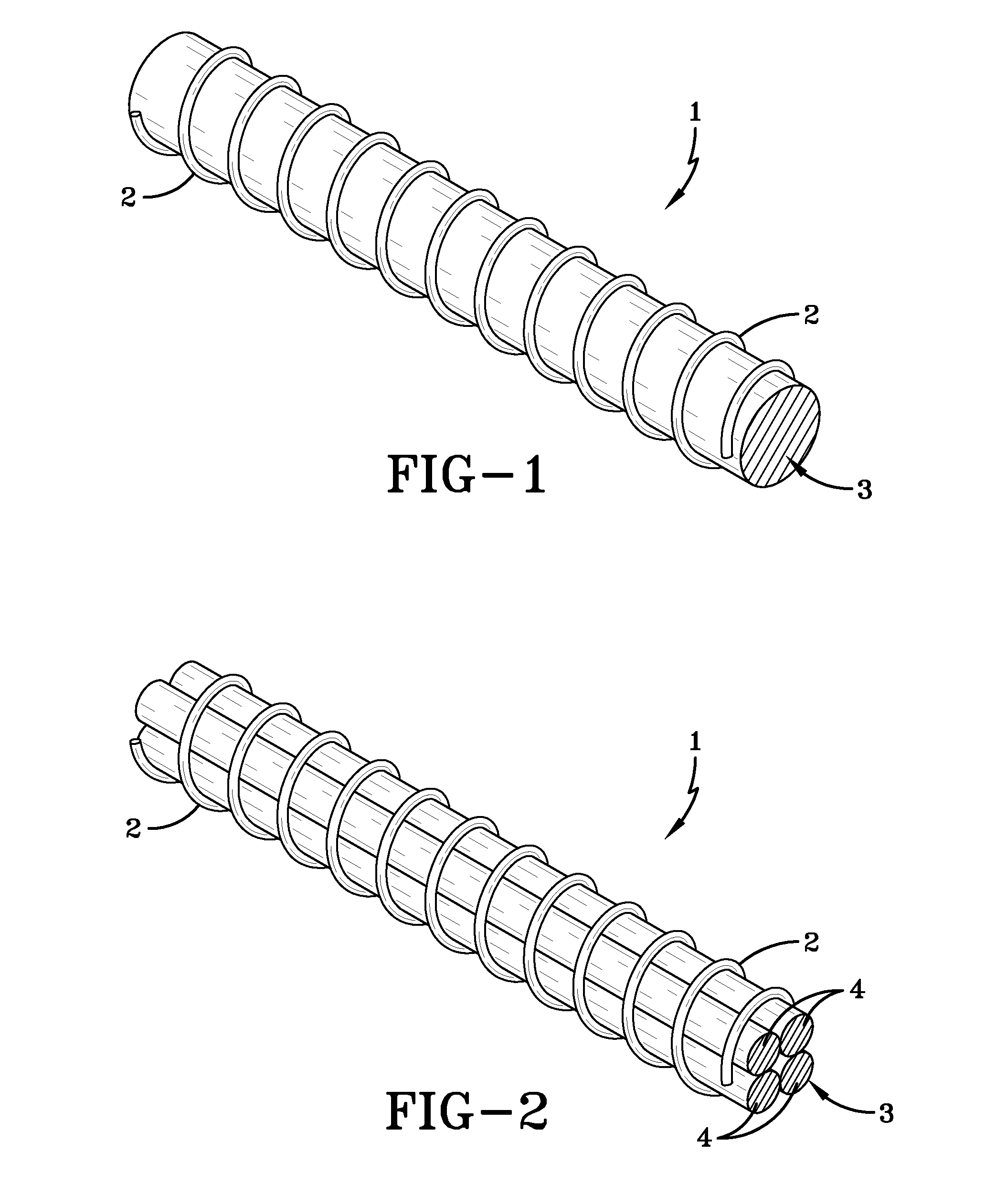
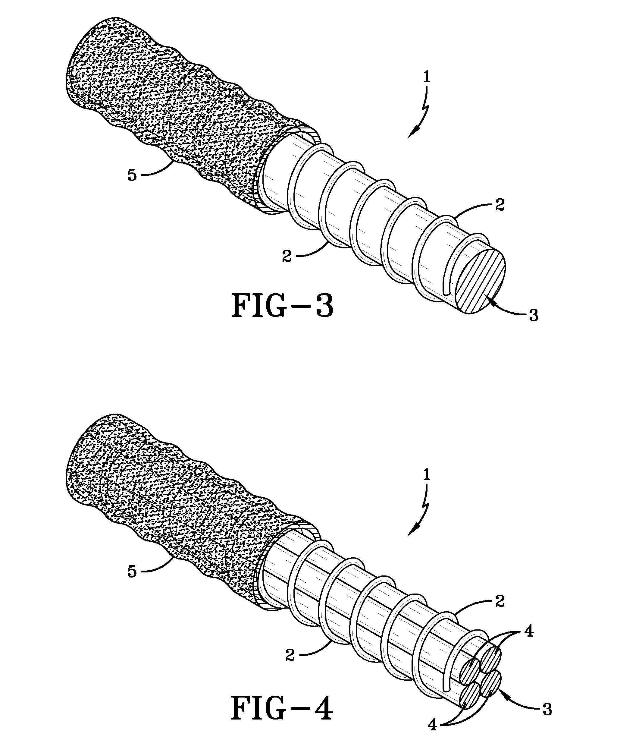
[0026]The conveyor belts of this invention include a rip detection sensor which is in the form of a microcoil sensor wire, wherein the microcoil sensor wire is configured in an endless loop and wherein the microcoil sensor wire is comprised of an elastomeric core having an electrically conductive wire spirally wrapped around the elastomeric core. Such a microcoil sensor wire 1 is illustrated in FIG. 1 wherein the electrically conductive wire 2 is spirally wrapped around a single elastomeric core 3. In another embodiment of this invention as depicted in FIG. 2 the elastomeric core 3 can be comprised of a plurality of elastomeric filaments 4 which form the elastomeric core 3. In any case, the elastomeric core 3 will be comprised of a rubbery material, such as a thermosetting rubber or a thermoplastic elastomer. For instance, the rubbery material can be natural rubber a synthetic rubber, such as a polydiene rubber. Some representative examples of materials that can be used as the elast...


PUM

PropertyMeasurementUnit
elongation to breakaaaaaaaaaa

Abstract

A conveyor belt comprising (1) an elastomeric body having a load carrying surface and a parallel pulley engaging surface; (2) a reinforcement ply disposed within the elastomeric body; (3) a rip detection sensor in the form of a microcoil sensor wire which is configured in an endless loop, wherein the microcoil sensor wire is comprised of an elastomeric core having an electrically conductive wire spirally wrapped around the elastomeric core.

Description

[0001]This application claims the benefit of U.S. Provisional Patent Application Ser. No. 61 / 911,138, filed on Dec. 3, 2013. The teachings of U.S. Provisional Patent Application Ser. No. 61 / 911,138 are incorporated herein by reference in their entirety.BACKGROUND OF THE INVENTION[0002]Conveyor belts are widely used for moving minerals, coal, and a wide variety of manufactured products from one point to another. Heavy duty conveyor belts used in mining operations can extend over distances of several miles and represent a high cost component of an industrial material handling operation. Unfortunately, such conveyor belts are susceptible to damage from the material transported thereon and a rip, slit, cut or tear may develop within the belt. For instance, sharp edges of the material being transported can gouge the surface of the belt and that can result in a rip developing.[0003]After being detected a torn or ripped belt can be repaired. However, the cost of repairing a heavy duty conv...

Claims


Application Information

Patent Timeline
Patent Type & Authority Patents(United States)
IPC IPC(8): B65G43/02H01B3/28H01B7/06B65G15/36
CPCB65G43/02H01B3/28H01B7/06B65G15/36B65G15/30B65G2203/0275B65G2203/042C22C9/00C22C9/06
Inventor WALLACE, JACK BRUCEEDWARDS, CHARLESLEIB, ROBERT EUGENE
Owner CONTITECH USA INC
Learn More