Induction fluorescent light fixture

a fluorescent light fixture and induction technology, applied in the direction of fixed installation, lighting and heating equipment, lighting applications, etc., can solve the problems of short lamp life, low lumen production per lamp, inefficient energy consumption, etc., and achieve the effect of convenient and economical high bay industrial lighting and more reliable trouble-fr

Inactive Publication Date: 2009-10-06
AMERICAN WHOLSALE LIGHTING
View PDF4 Cites 6 Cited by
  • Summary
  • Abstract
  • Description
  • Claims
  • Application Information

AI Technical Summary

Benefits of technology

[0022]The industrial lighting fixture contemplated according to the present invention utilizes induction fluorescent lighting in a new apparatus arrangement and departs substantially from the conventional concepts and designs taught and used by the prior art. In doing so, it provides an apparatus primarily developed for the purpose of overcoming the problems as described and enumerated above for various alternative types of lighting, but it accomplishes the result in a different and improved manner for producing more reliable trouble free high bay industrial lighting more conveniently and economically.
[0023]The use of induction fluorescent lighting in the present invention provides lamps with the longest life available and with the highest energy efficiency. The lamps are instant on with multiple switching. They can be provided in multiple color temperatures and provide a lamp with reduced glare. They utilize an energy efficient ballast with fewer parts to malfunction or fail providing greatly reduced maintenance costs and downtime. The lamps permit low / high temperature environment starting with low heat generation thereby effecting reduced heating, ventilating, and air-conditioning (HVAC) costs.

Problems solved by technology

These advantages are offset by short lamp life and inefficient energy consumption.
They provide lower lumen production per lamp which means limited use in high bay work spaces.
The disadvantages are: very bad color rendering; long strike time to illuminate; long re-strike time; expensive fixtures and lamp costs; ineffectual emergency lighting; and heat generation.
The disadvantages are: low color rendition; long strike time to illuminate; long re-strike time; expensive fixture and lamp costs; glare from the lamp; ineffectual emergency lighting; and heat generation.
The disadvantages are: color shifting over life; lumen depreciation over time; long strike time to illuminate; long re-strike time; expensive lamp and fixture costs; glare from the lamp; ineffectual emergency lighting; and heat generation.
The disadvantages are: high cost; glare from the lamp; ineffectual emergency lighting; and heat generation.
The disadvantages are: multiple lamps and ballasts are required to achieve the lumens needed; lower voltage restriction means fewer units on a circuit; temperature sensitive lamps and ballast; the multiple lamps and ballasts required are expensive to maintain; and high cost for the multiple units required.
The obvious disadvantages are: multiple lamps and ballasts required to achieve lumens needed; multiple lamps and ballasts costly to install and maintain; temperature sensitive lamps and ballasts; and lower voltages means fewer units on a circuit.
A more serious disadvantage for specific installations, however, it is the short life of the lamps.

Method used


Image

  • Induction fluorescent light fixture
  • Induction fluorescent light fixture
  • Induction fluorescent light fixture

Examples


Embodiment Construction

[0045]Reference is made to the drawings for a description of the preferred embodiment of the present invention wherein like reference numbers represent like elements on corresponding views.

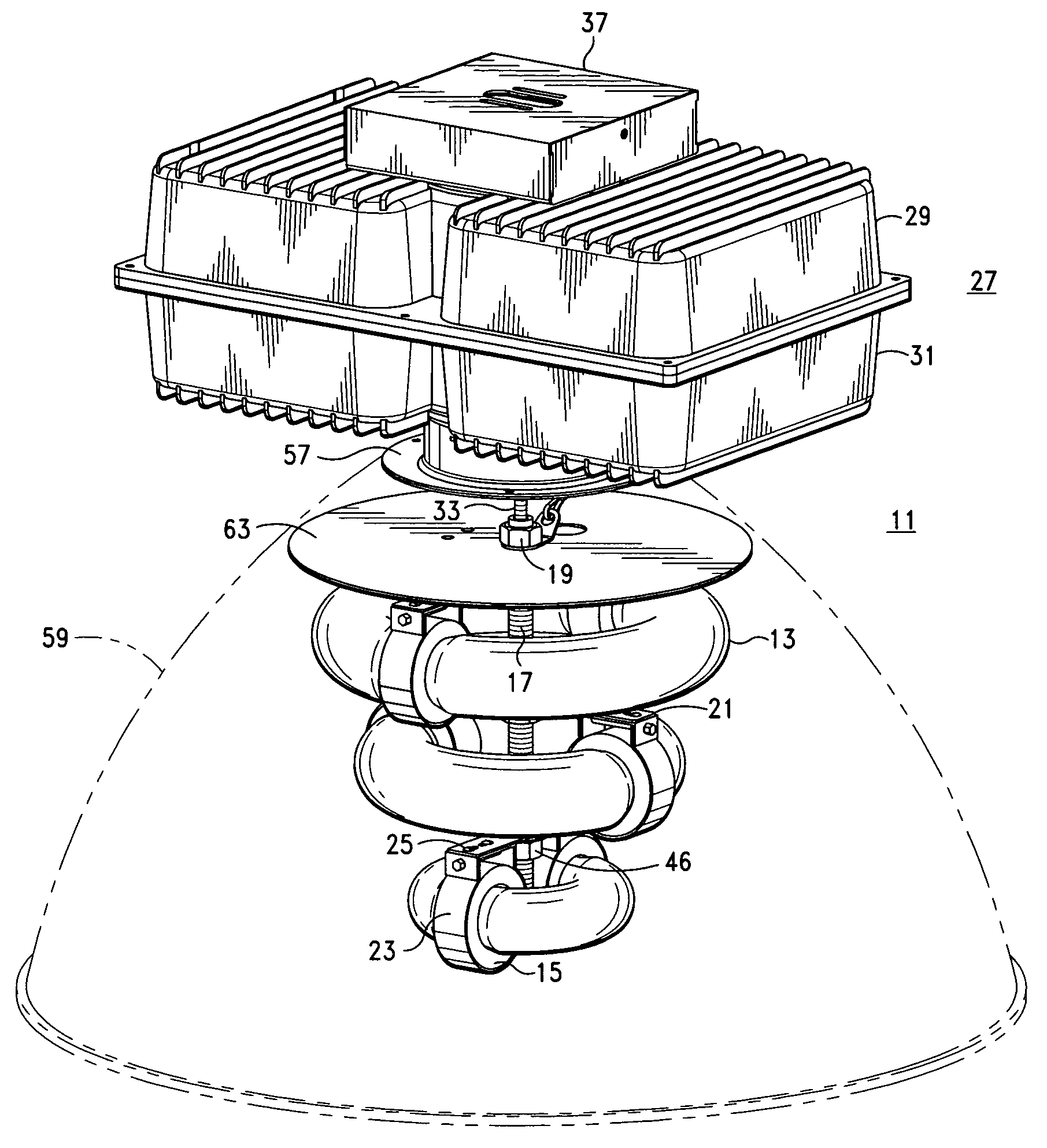
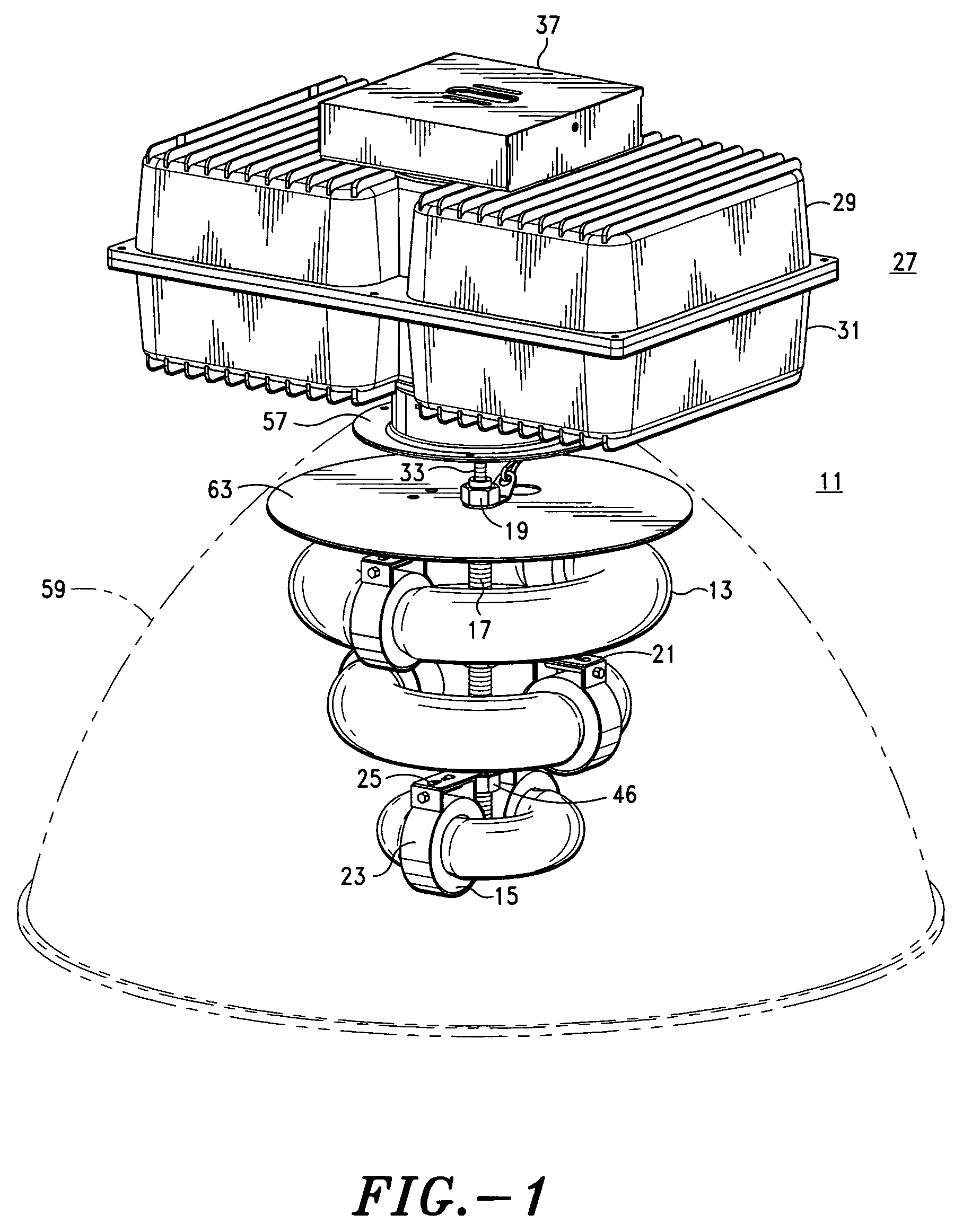
[0046]FIG. 1 is a perspective view of a preferred embodiment of the present invention which is an induction fluorescent three lamp industrial light fixture assembly 11 developed particularly for high bay industrial lighting. In a preferred embodiment of the invention, three circular independent induction fluorescent lamps 13 are utilized stacked in a predetermined configuration. Induction fluorescent lamps are high frequency light sources which follow the same basic principles of converting electrical power into visible radiation as conventional fluorescent lamps.

[0047]In comparison, conventional fluorescent lamps utilize electrodes to produce electrons which stimulate mercury vapor inside the fluorescent tube to emit UV radiation which in turn interacts with the fluorescent powder coated inside t...


PUM


Abstract

A high bay induction fluorescent lighting fixture having a multiple of nested circular lamps suspended on a post below the ballasts therefor and enclosed in a reflector.

Description

BACKGROUND OF THE INVENTION[0001]1. Field of the Invention[0002]The present invention relates to an apparatus for providing an improved fluorescent light fixture with optimized illumination performance most usually employed for industrial and commercial applications.[0003]More particularly the present invention provides a means for utilizing induction fluorescent lighting lamps for high bay industrial styled lighting fixtures as well as other applications.[0004]Still more particularly the present invention provides a new and novel apparatus for integrating single or multiple induction fluorescent lamps into a preferred configuration lighting fixture which provides maximum downward light dispersion from the assembled lamps.[0005]Specifically the present invention provides a new and novel lighting fixture for integrating a single or multiple of variable induction fluorescent lamps into a single unit with the required ballasts and reflector for optimum downward illumination to provide ...

Claims


Application Information

Patent Timeline
Patent Type & Authority Patents(United States)
IPC IPC(8): F21V7/10
CPCF21V19/0075F21V19/009F21V23/026F21S8/06F21Y2103/022F21W2131/40F21W2131/407F21Y2103/33
Inventor GARRETT, CLAYTON M.
Owner AMERICAN WHOLSALE LIGHTING
Why Eureka
Try Eureka