Temperature control method for use in a fusing device of an image forming apparatus having a fusing roller and a heater heating the fusing roller and image forming apparatus using the same

a technology of image forming apparatus and temperature control method, which is applied in the direction of electrographic process apparatus, instruments, optics, etc., can solve the problems of increasing power consumption, increasing and increasing the power consumption so as to minimize the fluctuation of the surface temperature and maintain the surface temperature of the fusing roller. , the effect of stably fusing

Active Publication Date: 2007-08-07
HEWLETT PACKARD DEV CO LP
View PDF9 Cites 9 Cited by
  • Summary
  • Abstract
  • Description
  • Claims
  • Application Information

AI Technical Summary

Benefits of technology

[0018]The present invention has been developed in order to solve the above and/or other problems in the related art. Accordingly, it is an aspect of the present invention to provide a temperature control method for use in a fusing device of image forming a...

Problems solved by technology

However, the aforementioned fusing device is not without disadvantages.
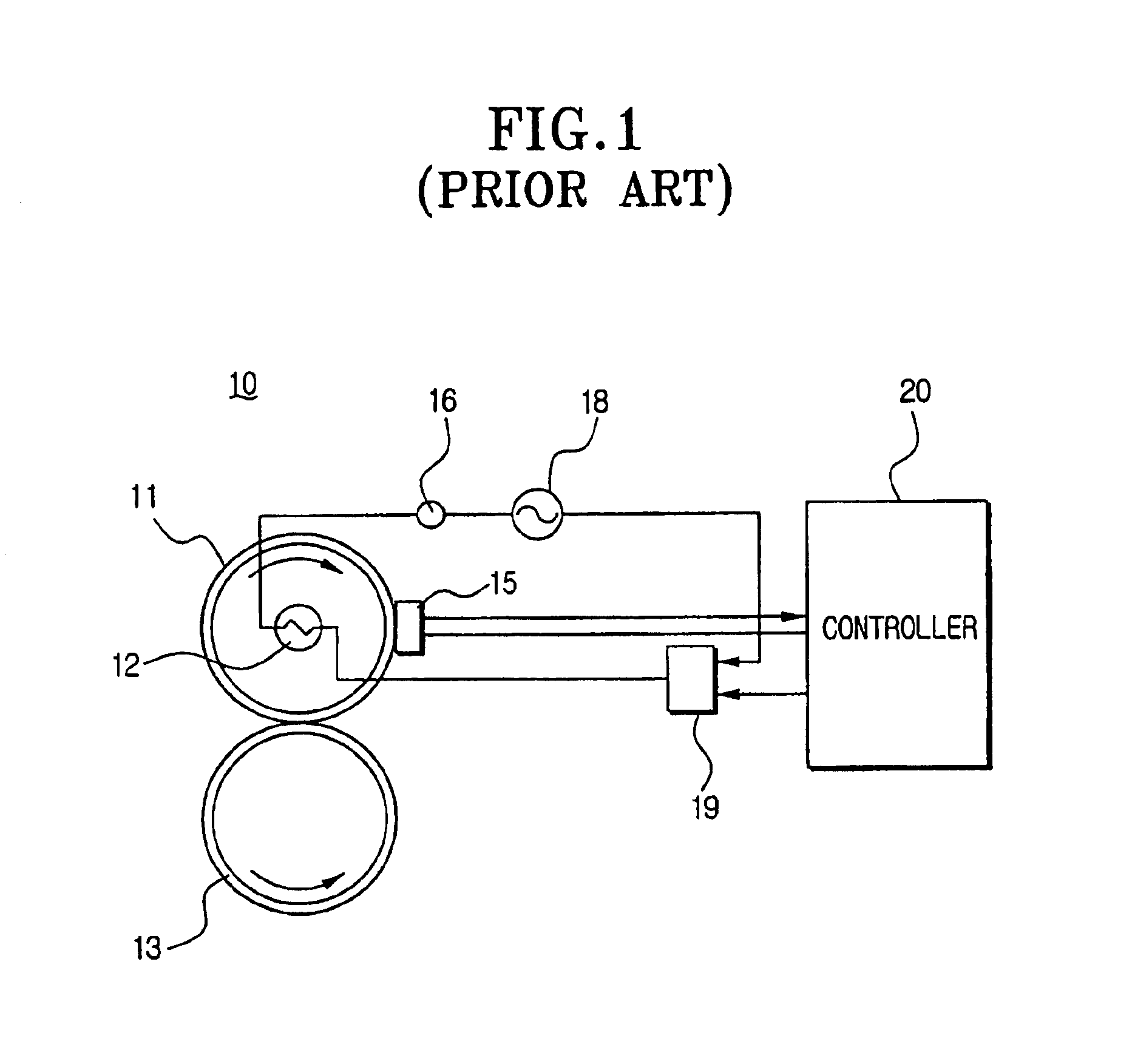
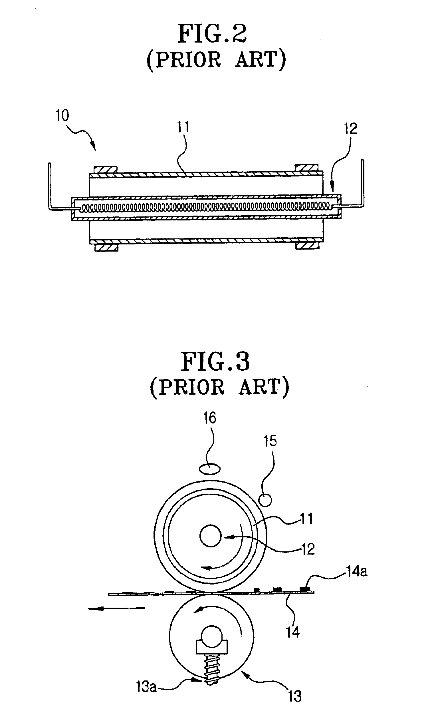
For example, in the conventional fusing device 10, since the halogen lamp 12 is turned on or off, regardless of a state or condition at each of the steps of the temperature control process for regulating the surface temperature of the fusing roller 11 in the print temperature, the electric power may n...

Method used


Image

  • Temperature control method for use in a fusing device of an image forming apparatus having a fusing roller and a heater heating the fusing roller and image forming apparatus using the same
  • Temperature control method for use in a fusing device of an image forming apparatus having a fusing roller and a heater heating the fusing roller and image forming apparatus using the same
  • Temperature control method for use in a fusing device of an image forming apparatus having a fusing roller and a heater heating the fusing roller and image forming apparatus using the same

Examples


Embodiment Construction

[0054]Reference will now be made in detail to embodiments of the present invention, examples of which are illustrated in the accompanying drawings, wherein like reference numerals refer to the like elements throughout. The embodiments are described below in order to explain the present invention by referring to the figures.

[0055]FIG. 4 schematically shows a part of a fusing device 100 of electrophotographic image forming apparatus, to which a temperature control method according to an embodiment of the present invention is applied.

[0056]The fusing device 100 includes a cylinder-shaped fusing roller 111 having a rubber layer on which a non-stick coating film 115, such as, by way of non-limiting example, TEFLON®, is coated, a fusing-backup roller (not shown) disposed under the fusing roller 111 to press the fusing roller 111 with a pressure, a heater 112, such as, by way of non-limiting example, a halogen lamp, is disposed in an inner center of the fusing roller 111 to generate a fusi...


PUM


Abstract

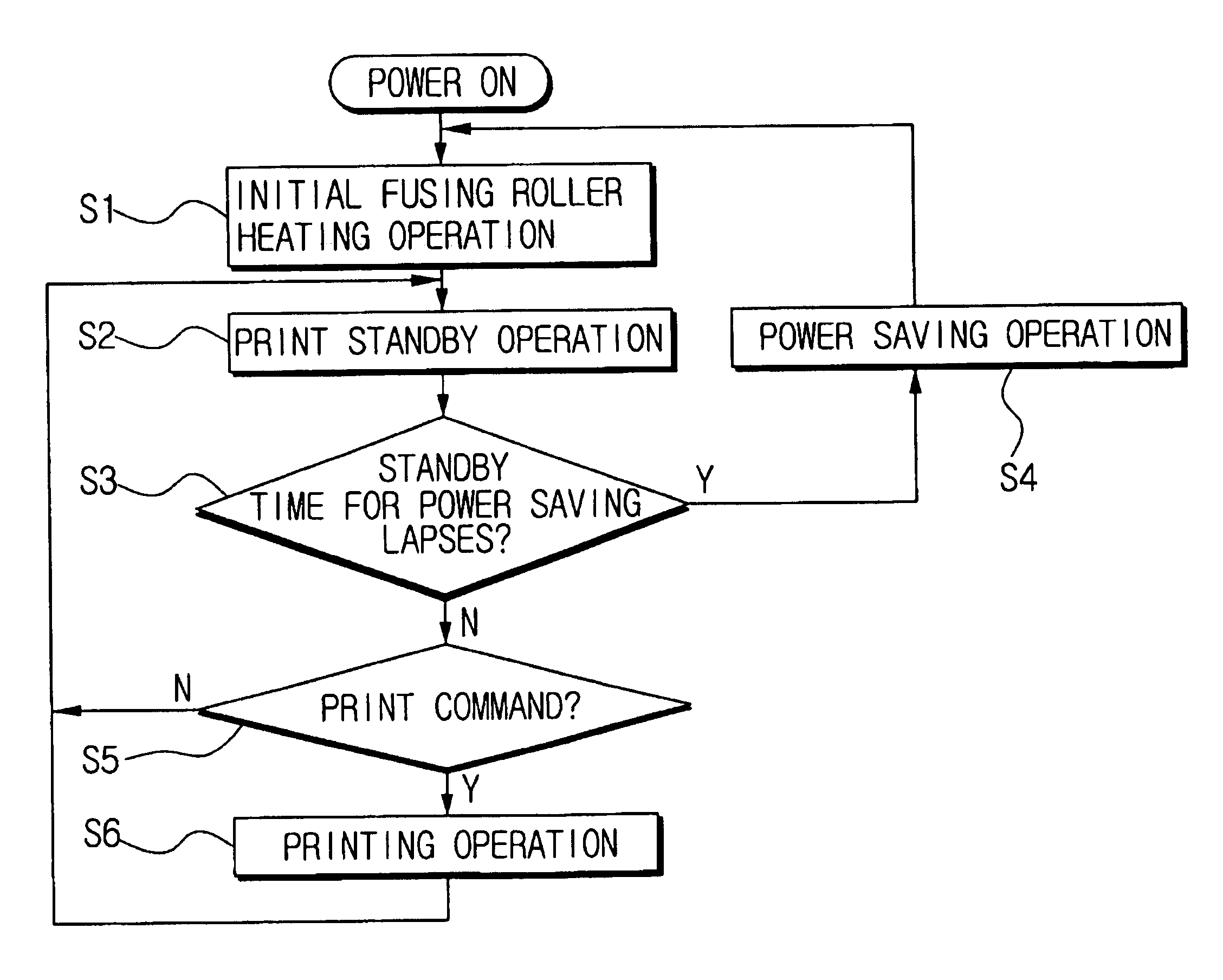
A temperature control method for use in a fusing device of image forming apparatus having a fusing roller and a heater heating the fusing roller, including: sensing a surface temperature T of the fusing roller at one of when the image forming apparatus is turned on, when the image forming apparatus begins a normal operation from a power saving operation, and when a cover of the image forming apparatus is closed after being opened; comparing the sensed surface temperature T of the fusing roller with a set temperature; driving the heater until the surface temperature T reaches a first target temperature Tt1 when the sensed surface temperature T is below the set temperature; and driving the heater until the surface temperature T reaches a second target temperature Tt2 when the sensed surface temperature T is over the set temperature.

Description

CROSS-REFERENCE TO RELATED APPLICATIONS[0001]This application claims the benefit of Korean Application No. 2003-895, filed Jan. 7, 2004, in the Korean Intellectual Property Office, the disclosure of which is incorporated herein by reference.BACKGROUND OF THE INVENTION[0002]1. Field of the Invention[0003]The present invention relates to fusing devices of image forming apparatus such as a laser beam printer, a multi-function machine, a photocopier, and the like, and more particularly, to a method of temperature control in a fusing device of an image forming apparatus by optimizing a power supply to a heater that heats a fusing roller of the fusing device and minimizing fluctuation in surface temperature of the fusing roller.[0004]2. Description of the Related Art[0005]Generally, an image forming apparatus such as a photocopier, a laser beam printer and the like, prints a desired image on a recording medium such as, a sheet of printing paper, by a series of image forming processes. The...

Claims


Application Information

Patent Timeline
IPC IPC(8): G03G15/20
CPCG03G15/205G03G15/5004G03G15/2057G03G2215/2051
Inventor LEE, BEOM-RO
Owner HEWLETT PACKARD DEV CO LP
Why Eureka
Try Eureka