Soil sampler apparatus and method

a soil sampling and soil technology, applied in the direction of instruments, foundation engineering, borehole/well accessories, etc., can solve the problems of inability to know how much fertilizer or other additives to place at a soil plot, manual operation to perform soil sampling is necessary, tiresome and time-consuming, etc., to achieve convenient operation, easy maintenance, and low cost

Inactive Publication Date: 2007-08-14
AGROBOTICS LLC
View PDF34 Cites 51 Cited by
  • Summary
  • Abstract
  • Description
  • Claims
  • Application Information

AI Technical Summary

Benefits of technology

[0016]It is therefore an object of the present invention to provide for a soil sampling mechanism that may automatically collect soil samples over an area of interest.
[0017]It is a further object of the present invention to provide for a soil sampling mechanism that provides sampling tubes that are stationary with respect to the ground during a portion of the sampling cycle so that the tube may be easily inserted and retracted from the ground in order to collect samples.
[0018]It is also an object of the present invention to provide for a soil sampling mechanism that is inexpensive to produce and easy to maintain.
[0019]It is also an object of the present invention to provide for a soil sampling mechanism that allows for the pneumatic movement of collected samples from a collection tray to a location more convenient to an operator.
[0020]It is also an object of the present invention to provide for a soil sampling mechanism that allows the automatic collection of a number of soil samples in a plurality of containers on a rotating tray for ease of analysis.
[0021]It is also an object of the present invention to provide for a soil sampling mechanism that allows for the use of a computer-based mapping system in order to map an area of interest and collect samples from the appropriate portions of the area of interest.

Problems solved by technology

The grower cannot know how much fertilizer or other additives should be placed at a plot of soil, however, without knowing the current level of nutrients and important minerals that are already present in each plot.
Various hand tools have been developed to somewhat ease the burden of this task, but any manual operation to perform soil sampling is necessary tiresome and time-consuming because of the expanse of land that must be covered when soil sampling is performed as part of a large-scale commercial farming enterprise.
The result is a poor approximation of the optimal nutrient level for each plot of soil, since some plots will likely be under fertilized and others will be over fertilized.
Under fertilized plots will produce poor yields, and over fertilized plots may both produce poorer than optimum yields and also result in a waste of fertilizers.
The wasted fertilizer not only is an added expense for the grower, but also exacerbates environmental issues that may arise from the later run-off of the excessive fertilizer due to rain or wind.
The use of GPS in conjunction with manual soil sampling, however, only provides modest improvements in accuracy and efficiency.
The automatic sampling mechanisms described above suffer from important disadvantages.
Mechanisms that simple scoop a sample of material from the top of the ground are undesirable since such a sample may not be representative of the lower levels of the soil in the area that is sampled.
A scooping mechanism will likely be unable to probe deeply enough to produce a sufficient sample to meet this need.
Although sampling mechanisms that insert a tube into the ground to collect a sample are superior to scoop mechanisms in many applications, the tube-type sampling mechanisms known in the art also suffer from disadvantages.
The process of inserting and removing a tube from a moving vehicle, however, presents a number of difficulties.
Depending upon the hardness of the soil, however, this may create a great deal of stress upon the tube.
While this may be a workable solution in very loose, highly compressible soil, this will likely lead to bending, excessive wear, or other damage to the tube in more firmly packed soil, or soil that may contain rocks or other hard obstacles.
While this arrangement may avoid the problems presented by tube rotation, the structure and linkages necessary for this functionality are complex, and would likely be expensive to manufacture and difficult to maintain.
Another disadvantage of the systems described above is that they do not take advantage of the efficiencies that may be achieved with the use of GPS information during sampling.

Method used


Image

  • Soil sampler apparatus and method
  • Soil sampler apparatus and method
  • Soil sampler apparatus and method

Examples


Embodiment Construction

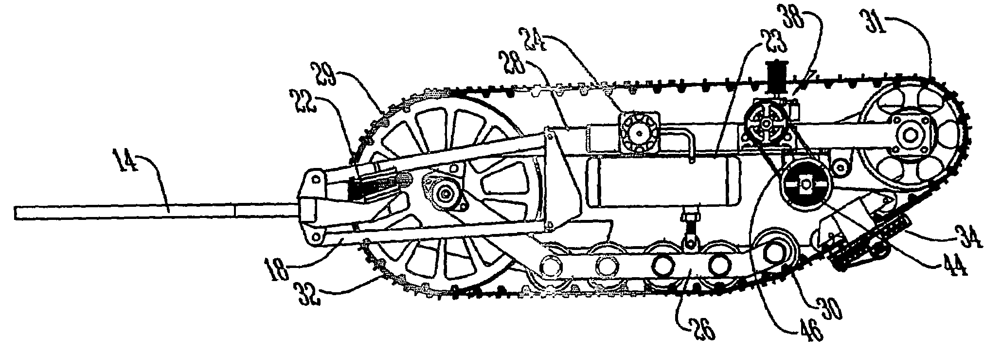
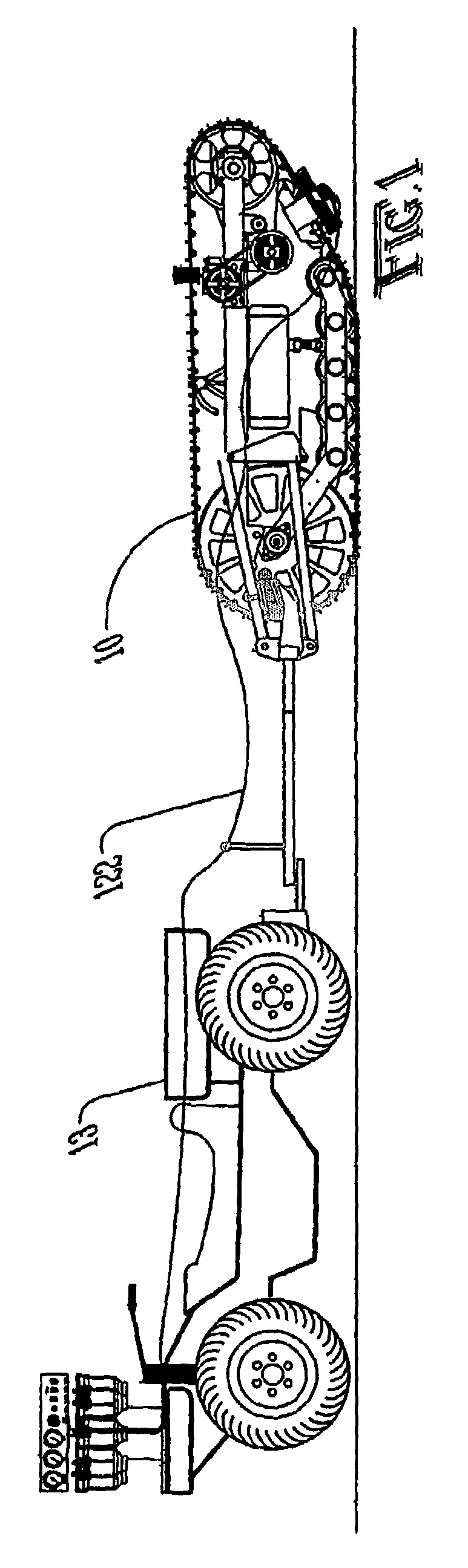
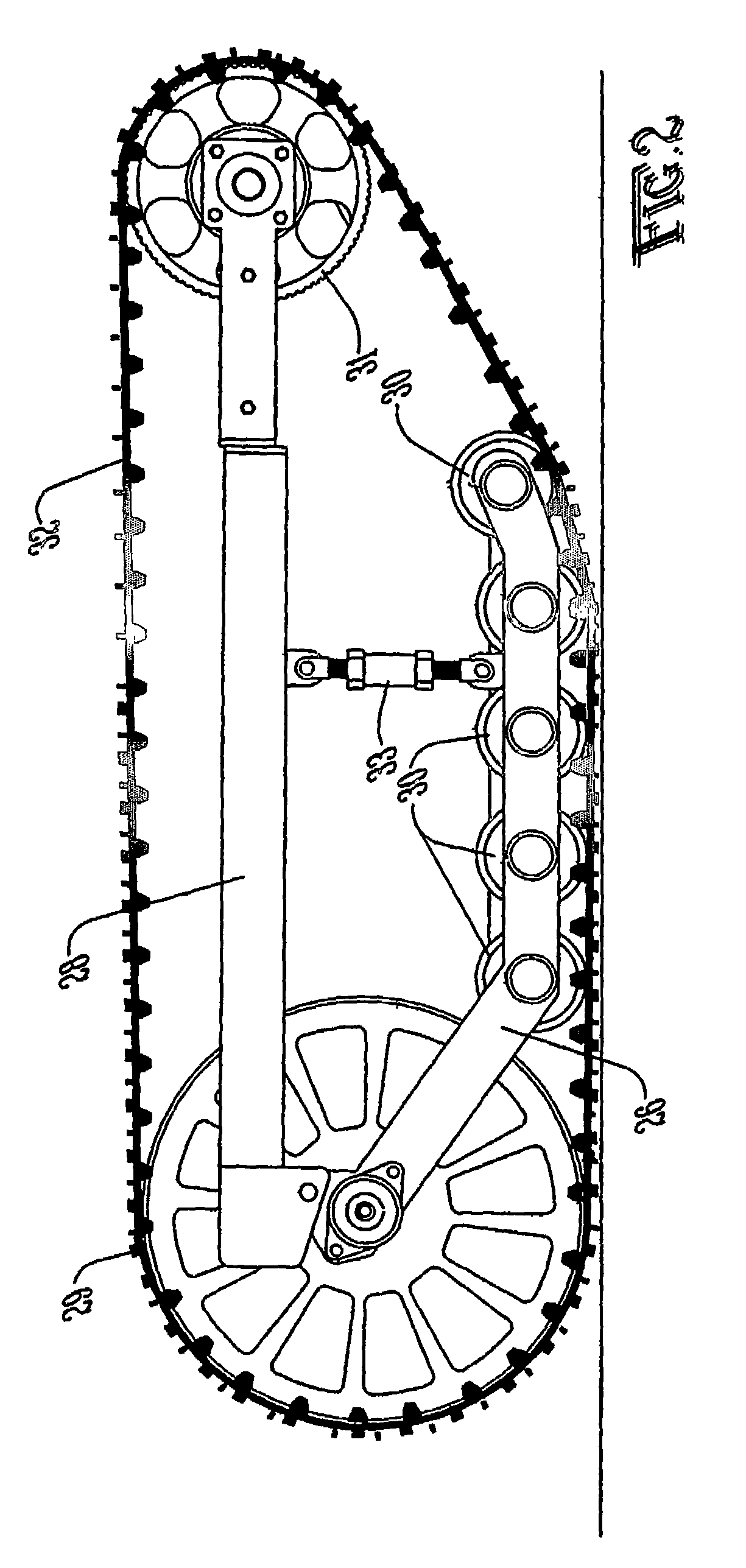
[0041]With reference to FIGS. 1-4, the preferred embodiment of the present invention may be described. The support structure of the preferred embodiment is provided by a trailer 10, which may include a U-shaped frame 12, a tongue 14, and support wheels 16. These components provide support for drive mechanism 17. In the preferred embodiment, wheels 16 are standard automobile wheels with rubber tires, but various other forms of wheels 16 may be employed such that trailer 10 may be easily pulled across cultivated soil as well as ferried to and from the field along paved or unpaved roads. Tongue 14 may be hitched to an all-terrain vehicle (ATV), tractor, or other powered vehicle 13 for the movement of the preferred embodiment in the field or other region where sampling is desired. Although the preferred embodiment of the invention is not powered, and thus relies on vehicle 13 for movement, alternative embodiments might include any form of drive mechanism 17 that is integrated with the o...


PUM

PropertyMeasurementUnit
widthaaaaaaaaaa
widthaaaaaaaaaa
massaaaaaaaaaa

Abstract

An apparatus removes soil samples at intervals over a field of interest. The apparatus comprises a sampling assembly (60) that rotates on a track (32) riding on a plurality of idler wheels (29, 31). A probe (66) extends and retracts under the action of a scissored frame assembly (70), mechanically manipulated by passage of the scissored frame assembly (70) along a guide assembly (108). The probe (66) is extended into the ground and retracted on each revolution. An ejector (68) pushes soil from the probe (66) as it passes over a hopper (88) to retain the cores. The cores are pneumatically transferred from the hopper (88) to a plurality of sample collection containers (126). An electronic control system uses GPS location information to deposit collected cores in the appropriate container (126) based upon the current location of the apparatus in the field of interest.

Description

[0001]This application is the National Stage of International Application No. PCT / US2004 / 007183, filed Mar. 9, 2004, which claims the benefit of U.S. Provisional Application No. 60 / 454,460, filed Mar. 13, 2003, both of which are incorporated herein by reference.TECHNICAL FIELD[0002]The present invention relates to soil sampling devices and methods, and in particular to soil sampling devices that periodically and automatically take soil samples over an area of interest, and related methods.BACKGROUND ART[0003]In order to optimize the production capacity of any agricultural land, the grower must provide in each plot of soil the amount of fertilizers and other nutrients and additives that will render each plot ideal for the crop that is to be sewn and harvested. The grower cannot know how much fertilizer or other additives should be placed at a plot of soil, however, without knowing the current level of nutrients and important minerals that are already present in each plot. The quantit...

Claims


Application Information

Patent Timeline
Patent Type & Authority Patents(United States)
IPC IPC(8): E21B49/02G01N1/04E02D1/04
CPCE02D1/04E21B7/027E21B49/02G01N1/08G01N2001/021
Inventor BURTON, JAMES D.
Owner AGROBOTICS LLC
Why Eureka
Try Eureka