
Carburetor with adjustable air bypass

a carburetor and air bypass technology, which is applied in the field of carburetors, can solve the problems of poor idle, difficult to set the proper amount of air and fuel flow to the engine during idle, and affect the performance of the engine, so as to eliminate the long-standing poor idle and the effect of reducing the number of idles

Active Publication Date: 2007-08-14
HOLLEY PERFORMANCE PRODUCTS
View PDF11 Cites 22 Cited by
  • Summary
  • Abstract
  • Description
  • Claims
  • Application Information

AI Technical Summary

Benefits of technology

This solution enables precise adjustment of the air-to-fuel ratio at idle speed, preventing rich or lean conditions and stabilizing engine performance by delivering clean air without overloading the engine with fuel, thus improving idle stability and preventing stumbles.

Problems solved by technology

With a high performance engine having a carburetor that controls the mixture of air and fuel to the engine, it is difficult to set the proper amount of air and fuel flow to the engine during idling of the engine.
If there is too much fuel in the air moving to the combustion chambers, the engine will idle rich.
A rich condition produces problems ranging from an exhaust that is foul smelling and hard on the eyes to fouled sparkplugs that affect the performance of the engine.
If there is not sufficient fuel present with respect to the air, the engine will idle lean.
A lean condition will lead to a hesitation or “stumble” of engine performance when the throttles are opened in an attempt to accelerate the engine.
It is with this butterfly adjustment that a common problem with adjusting carburetors at idle appears.
It is this low pressure that leads to a difference in pressure with the atmosphere that causes air to move through the carburetor and draw fuel to be discharged into the engine.
The problems mentioned above of poor idling and engine stumble usually occur if the butterfly is open too much during idle speed and as a result too much of the transfer slot is exposed to low pressure, drawing more fuel from the transfer slot and there is not enough fuel left in the reserve fuel supply to cover the transition from idle to main circuit operation.
One of the greatest causes of this open butterfly condition results when an engine produces very little signal (vacuum) at idle.
This generally leads to a rich idle, and a stumble off idle due to the fact that the fuel reserve that feeds the transfer slot is out of fuel.

Method used


Image

  • Carburetor with adjustable air bypass
  • Carburetor with adjustable air bypass
  • Carburetor with adjustable air bypass

Examples


Embodiment Construction

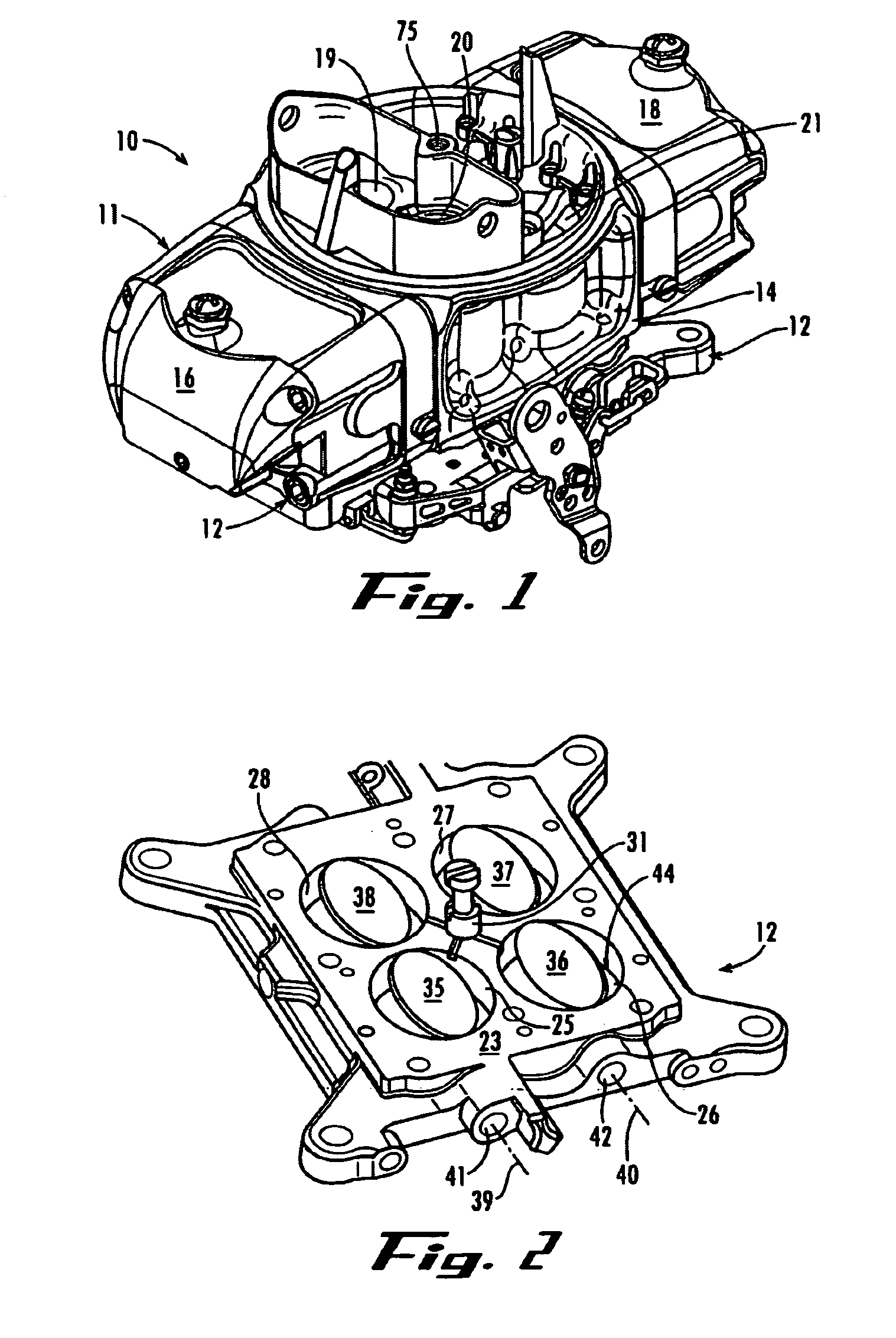
[0017]Referring now in more detail to the drawings, in which like numerals indicate like parts throughout the several views, FIG. 1 illustrates a carburetor assembly 10 having a carburetor body 11 mounted on a base plate 12. The carburetor body includes the typical structural features, such as a center section 14 having four venturis arranged in a square array such as venturis 19, 20 and 21, and opposed fuel bowls 16 and 18 mounted on the sides of the center section.

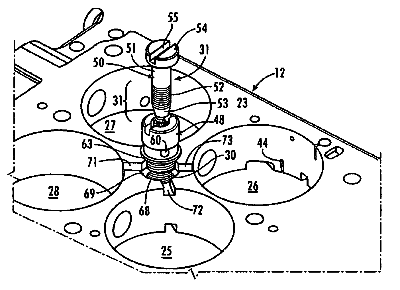
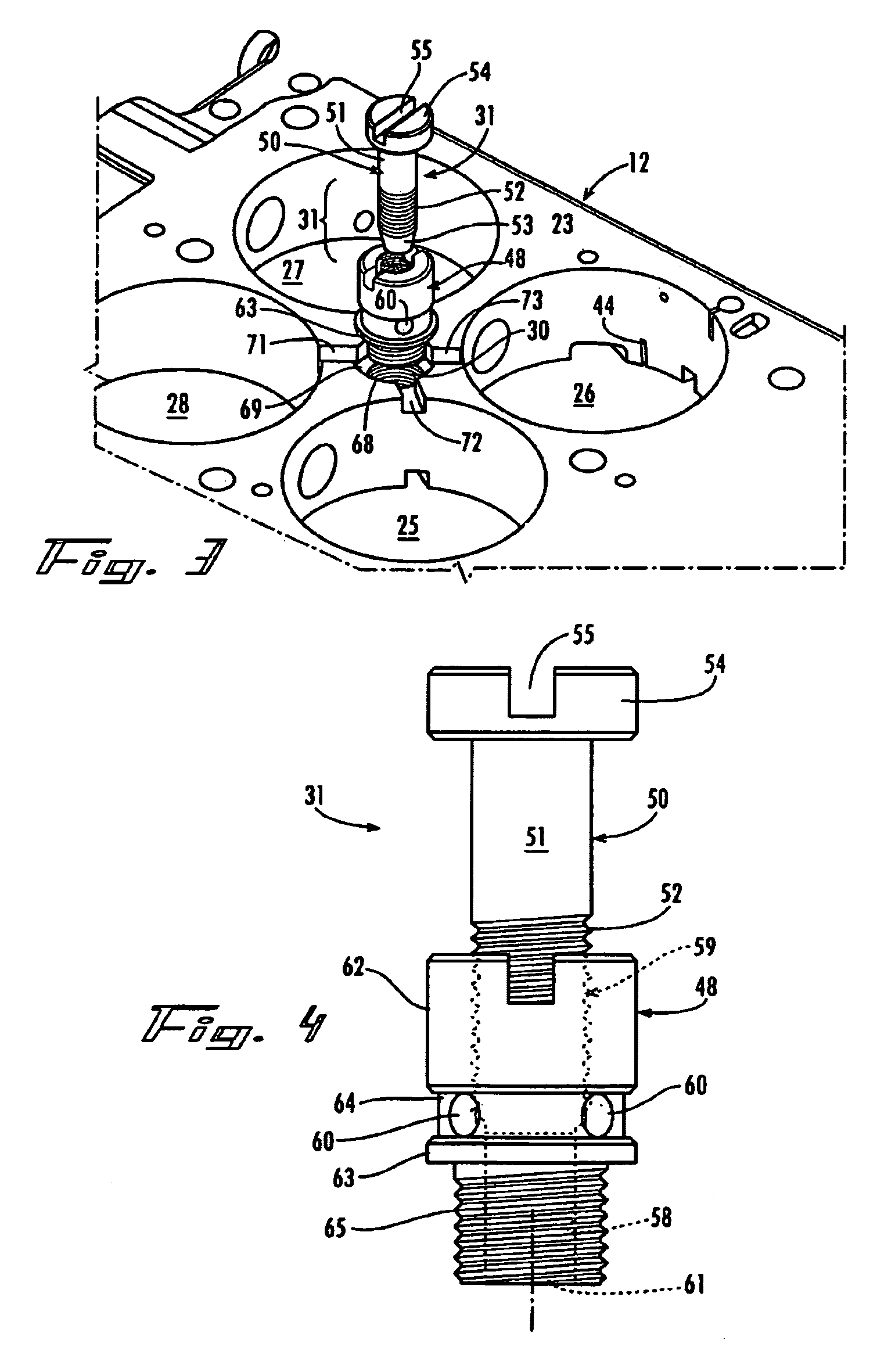
[0018]FIG. 2 illustrates the base plate 12 in more detail. The base plate is generally of square configuration and includes an upper surface 23 and an opposing lower surface (not shown), with butterfly bores 25, 26, 27 and 28 extending therethrough. The butterfly bores are arranged in a square array in the base plate, and an air bypass passage 30 is positioned centrally among the butterfly bores. An adjustable air bypass valve 31 is mounted in the air bypass passage 30.

[0019]Butterfly valves 35, 36, 37 and 38 are tiltabl...


PUM

PropertyMeasurementUnit
volumeaaaaaaaaaa
sizeaaaaaaaaaa
speedaaaaaaaaaa

Abstract

A carburetor assembly includes a base plate (12) having an air bypass passage (30) extending there through, with air channels (71-74) formed in the surface of the base plate intersecting the air bypass passage and each of the butterfly bores (25-28) of the base plate. An adjustable air bypass valve (31) is mounted on the base plate and controls the movement of air through the bypass passage. A valve needle (50) is adjustably mounted to the valve body (48) for adjustably constricting the flow of fluid through the radially extending air inlet ports (60) and through the base plate air bypass passage, to allow for the adjustment of the volume of the air delivered to the engine at idle speed, independently of the movements of the butterfly valves.

Description

CROSS REFERENCE[0001]Applicant claims the benefit or Provisional Patent Application 60 / 512,075 filed in the U.S. Patent and Trademark Office on Oct. 17, 2003.FIELD OF INVENTION[0002]This invention concerns carburetors for high performance internal combustion engines for vehicles. More particularly, the invention concerns an adjustable air bypass for a carburetor assembly that allows some of the air to move through the carburetor body and its base plate and to reach the engine substantially without adding fuel to the air, and for adjusting the flow of the air independently of the function of the butterfly valves.BACKGROUND OF THE INVENTION[0003]It is well known that an internal combustion cylinder / piston engine requires the proper mixture of air (oxygen) and fuel (gasoline) for optimum performance. Also, the optimum mixture of fuel and air tends to vary as the speed of the engine changes. This is evident when the engine is operating a idle speed and then is rapidly accelerated.[0004]...

Claims


Application Information

Patent Timeline
Patent Type & Authority Patents(United States)
IPC IPC(8): F02M19/10F02D9/10F02M3/14F02M23/06
CPCF02D9/1055F02M3/14F02M23/06Y02T10/146Y02T10/12
Inventor GRANT, BARRY S.
Owner HOLLEY PERFORMANCE PRODUCTS
Learn More