Power plug

a power plug and plug-in technology, applied in the field of plugs, can solve the problems of reducing the life of a frequently used plug and compromising the quality of life, and achieve the effects of reducing the space used by electrical equipment, avoiding harm, and high safety

Active Publication Date: 2007-08-14
WELL SHIN TECH
View PDF5 Cites 39 Cited by
  • Summary
  • Abstract
  • Description
  • Claims
  • Application Information

AI Technical Summary

Benefits of technology

[0008]In summary, the plug, by the three internal structures, might revolve at 360-degrees. Allowing the avoidance of harm caused by bending plug wires. Further, the 360-degree structure reduces the space used by electrical equipment and achieves the purpose of high security and high convenience.

Problems solved by technology

Since the contact area of the friction is too wide, it will reduce the life of a frequently used plug, and may compromise the quality of life.

Method used


Image

  • Power plug
  • Power plug
  • Power plug

Examples


Embodiment Construction

[0026]A power plug 1, according to preferred embodiments of the present invention, is illustrated in the figures, and provides the functional arrangement and formation to reduce the compromise on the quality of life.

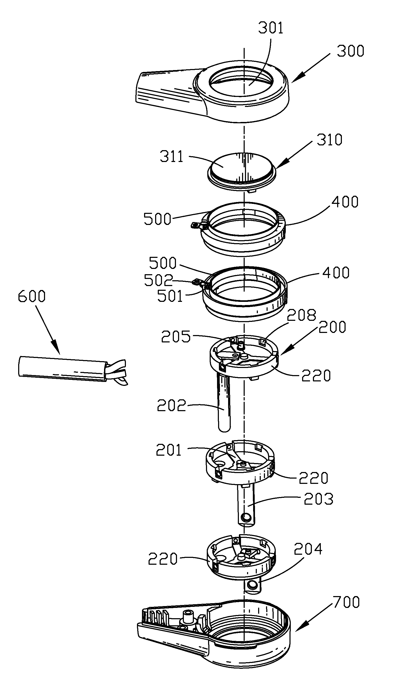
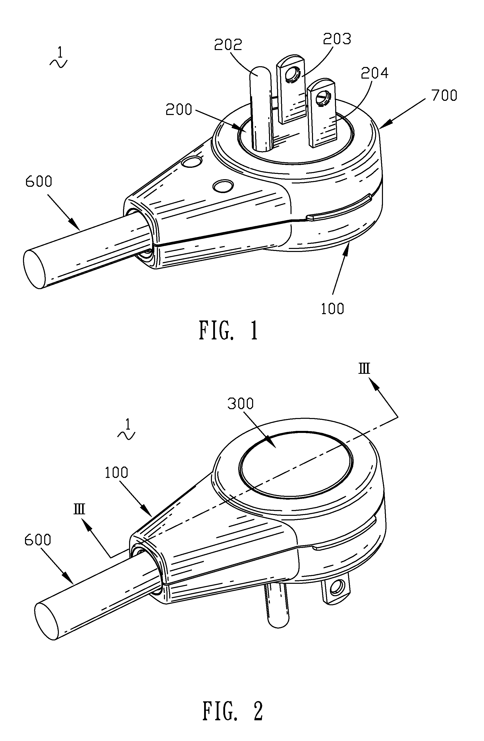
[0027]Referring to FIG. 1 and FIG. 2, the power plug 1 includes a hollow housing 100. The hollow housing 100 includes a top cover 300. A foot cover 700 is coupled to the top cover 300. A rotating base 200 is mounted in a limitative set 400 (not shown). The limitative set 400 is mounted in the interior of the hollow housing 100. The end of the hollow housing 100 defines a wire hole where a wire 600 is received. Blades 202, 203 and 204 extend outwards from the rotating base 200.

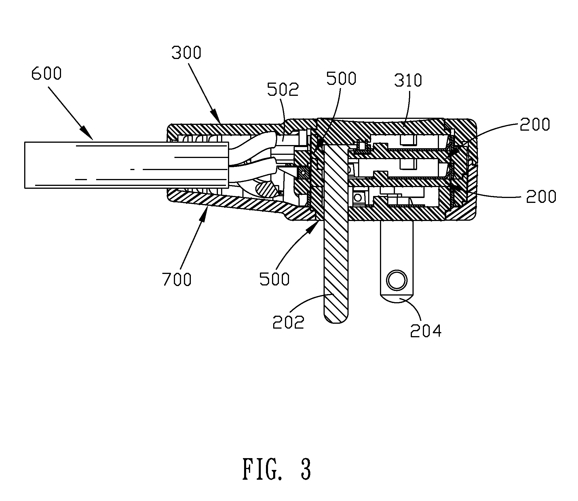
[0028]Referring to FIG. 3 and FIG. 4, a rotating cover 310 is mounted on the top cover 300. Three rotating bases 200 are mounted from the top to the bottom between the top cover 300 and the foot cover 700. Each of the rotating bases 200 fastens the blades 202, 203 and 204 respectively. The wire 600 ...


PUM


Abstract

A power plug, comprising: a hollow housing, with a wire hole in the end. A limitative set is contained within the hollow housing. There are also at least two bases, placed in the limitative slot and revolvingly contacting to each slip ring, are insulated by the loop located within the limitative set, and at least two blades. The ring rim of each base extends upward to form a ring wall. The ring wall defines at least a notch through the lateral plane of the ring wall, and the inside of the ring wall contains a contact piece. The contact piece has a contact arm that is embedded in the notch. The tip of the contact arm bends to form a contact part and extends out of the notch to tightly contact the contact piece by the contact part. Each of the blades that is mounted in each base electrically contacts the contact piece.

Description

BACKGROUND OF THE INVENTION[0001]1. Field of the Invention[0002]The present invention relates to a plug, particularly to a power plug.[0003]2. The Related Art[0004]U.S. Pat. No. 6,595,782 issued on Jul. 22, 2003 discloses a conventional power plug. The conventional power plug normally has a housing, at least two connecting blades, at least two disks securely received in the housing, at least two slip rings each mounted on one of the two disks and power relative to the corresponding disk, and at least two securing elements each received in the housing to securely engage with the corresponding slip ring. After the two slip rings are securely connected to the securing elements and the two connecting blades are electrically connected to the two disks, the plug is able to rotate regardless of the connection between the two connecting blades and a power socket firmly fixed at a location.[0005]The rotation of the power plug in this patent is accomplished between the slip ring and the colle...

Claims


Application Information

Patent Timeline
Patent Type & Authority Patents(United States)
IPC IPC(8): H01R39/00B60C19/00
CPCB60C19/002H01R39/64H01R24/30
Inventor WU, JUI-HSIUNG
Owner WELL SHIN TECH
Why Eureka
Try Eureka