System and method for transmitting data on return path of a cable television system

a return path and cable television technology, applied in the field of upstream data communication, can solve the problems of inability to take information back from subscribers, the equipment is so expensive that it cannot be cost justified today, and the ingress path signals need to be aggregated, so as to avoid or substantially reduce the aggregation, ingress and/or link degradation related problems, and the effect of efficient use of optical fiber links

Inactive Publication Date: 2007-08-14
II VI DELAWARE INC
View PDF40 Cites 66 Cited by
  • Summary
  • Abstract
  • Description
  • Claims
  • Application Information

AI Technical Summary

Benefits of technology

[0026]The present invention provides a new return path apparatus and return path signal transmission method that avoids or substantially reduces the aggregation, ingress and / or link degradation related problems currently found in return path links. Further, the return path apparatus of the present invention also provides efficient use of the optical fiber links by transmitting data from more than one RF data channel.

Problems solved by technology

Since the purpose was to distribute television channels throughout a community, the systems were designed to be one-way and did not have the capability to take information back from subscribers to the head end.
With the advent of these advanced services, there also arose numerous problems with using a physical CATV plant designed to transmit video signals from town council meetings (using the forward path) to provide high-speed Internet access for hundreds, if not thousands, of users simultaneously (using both the forward and return path).
Economically, the main problem that exists for CATV return path technology is that the return path signals need to be aggregated; which means the signals from many users are summed into a combined signal.
Return signals are summed because processing the return path signals from their multi-frequency radio frequency (RF) format to digital packets ready for the Internet requires the use of an expensive device called a CMTS (cable modem termination system).
This equipment is so expensive that it cannot be cost justified today on the basis of processing only one or even a couple of return signals.
Most HFC systems provide only a small number of optical fibers for each neighborhood, and thus these systems do not have enough optical fibers to provide a separate optical fiber for each return signal.
Aggregation, when done by simply combining various RF level signals from the return signals of individual users, results in a degradation of the signal to noise ratio (SNR) for the system.
A problem known as “ingress” is often made much worse by the aggregation of many RF signals.
The noise signals typically injected into the return paths of CATV systems are of unpredictable frequency and strength.
This is ingress and it can result in the loss of data for the other ninety-nine well-behaved users!
Analog optical fiber return path links suffer from another problem.
The links degrade with distance and connector problems.
Connector and splice problems can cause a degradation in the laser relative intensity noise (RIN), and all of these phenomena, including back scattering, cause light arriving at the receiver to have traveled different distances down the fiber and hence some of the arriving light can be out of phase with the transmitted RF signal.
Link degradation also can occur from the substantial temperature swings associated with the outdoor environment through which return path links travel, as well as rough handling of the return path link equipment by installers, for example during the installation of equipment at the top of poles.
The system in FIG. 1 conforms generally to 1999 industry standards, and is susceptible to the ingress and link degradation problems described above.
DFB lasers are used in conjunction with an optical isolator and have improved signal to noise over FP lasers, but at a sacrifice of substantial cost.
Another shortcoming of the prior art return path link systems is inefficient use of the fiber optic links.

Method used


Image

  • System and method for transmitting data on return path of a cable television system
  • System and method for transmitting data on return path of a cable television system
  • System and method for transmitting data on return path of a cable television system

Examples


Embodiment Construction

Return Path Dual RF Signal Transmitter

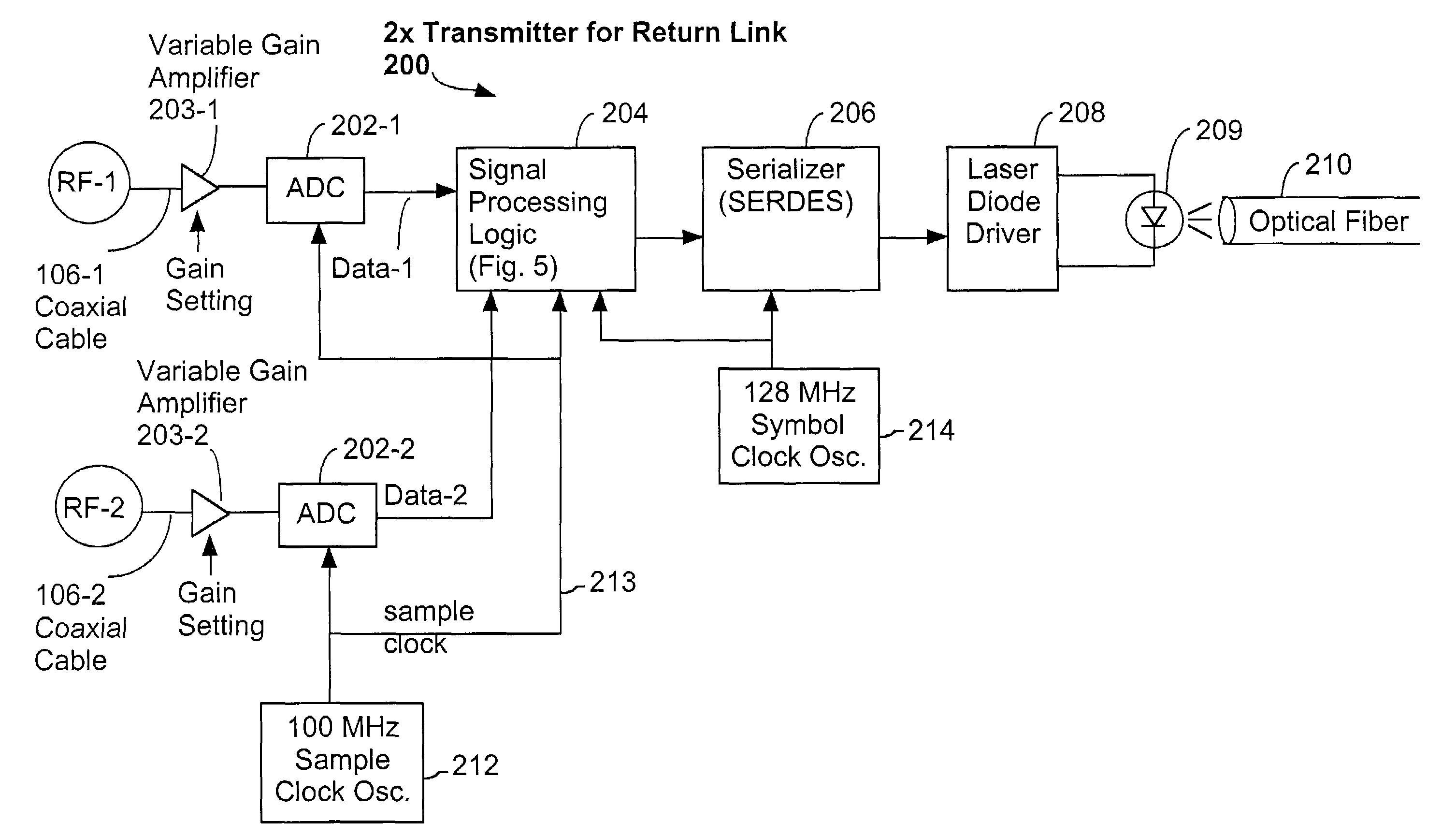
[0054]Referring to FIG. 4, there is shown a preferred embodiment of a dual RF channel transmitter 200 of a digital return path link of the present invention. In particular, the transmitter 200 is preferably configured to receive two radio frequency (RF) signals from two separate coaxial cables 106-1, 106-2. Each RF signal is processed by a variable gain amplifier 203-1, 203-2 and digitized by a pair of analog to digital converters (ADC) 202-1, 202-2. As will be discussed in more detail below, in some embodiments of the present invention the gain of each variable gain amplifier 203 is controlled via commands received from the head end of the system. These commands are received by a control logic circuit 227 (shown in FIG. 5) which uses the commands to set the gain of the amplifiers 203, as well as to set the mode of other components of the transmitter 200.

[0055]It should be understood by the reader that all clock rates, data structures and the li...


PUM


Abstract

An optical signal return path system includes a transmitter having a sample clock generator for generating a sample clock and an RF signal receiver for receiving and converting an analog RF data signal into a first data stream of digitized RF data samples at a rate determined by the sample clock. Supplemental channel circuitry provides a second data stream. A multiplexor receives and combines the first data stream and second data stream, and an optical transmitter converting the combined data stream into a serialized optical data signal for transmission over an optical fiber. The second data stream may contain maintenance data reflecting an operational state of the transmitter. A receiver receives the optical data signal and recovers therefrom a digital data stream and an associated first clock having an associated first clock rate. The data stream is stored in a memory device at the first clock rate. A clock generator generates a second clock having an associated second clock rate that is adjusted in accordance with a clock control signal. A control circuit reads data from the memory device at a rate corresponding to the second clock rate and generates a fullness signal that indicates whether the memory device is more full than a predefined threshold fullness level. A clock speed adjusting circuit generates the clock control signal in accordance with the fullness signal.

Description

CROSS-REFERENCE TO RELATED APPLICATIONS[0001]This application claims the benefit of U.S. Provisional Application No. 60 / 170,413, filed on Dec. 13, 1999.FIELD OF INVENTION[0002]The present invention relates generally to upstream data communications over networks primarily designed for downstream transmission of television and data signals, and particularly to a system and method for converting one or more analog signals into digital signals, transmitting them over optical media, and then accurately regenerating the one or more analog signals.BACKGROUND OF THE INVENTION[0003]Basic CATV System Architecture. Cable television systems (CATV) were initially deployed so that remotely located communities were allowed to place a receiver on a hilltop and then use coaxial cable and amplifiers to distribute received signals down to the town which otherwise had poor signal reception. These early systems brought the signal down from the antennas to a “head end” and then distributed the signals ou...

Claims


Application Information

Patent Timeline
Patent Type & Authority Patents(United States)
IPC IPC(8): H04B10/04H04B10/00H04L13/08H04L69/40H04N7/173H04N7/22H04N21/61
CPCH04N7/17309H04N7/22H04N21/615H04N21/6168H04N7/10
Inventor LEVINSON, FRANK H.SAGE, GERALD F.LAWSON, ARTHUR MICHAELMOSTERT, WILLEM A.
Owner II VI DELAWARE INC
Why Eureka
Try Eureka