Patient-worn medical monitoring device

a monitoring device and patient technology, applied in the field of medical monitoring devices, can solve the problems of not being able to allow normal patient ambulation, requiring special attention to move along with the patient, and devices remain too heavy and bulky, and achieve the effect of low applied cos

Inactive Publication Date: 2007-08-14
DATASCOPE INVESTMENT
View PDF6 Cites 394 Cited by
  • Summary
  • Abstract
  • Description
  • Claims
  • Application Information

AI Technical Summary

Benefits of technology

[0013]Accordingly, it is an object of the invention to produce an arrangement of electrodes or other signal sensors or electronics and a mechanical attachment to the patient for said sensors or electronics, which provide convenience, comfort, dignity and low applied cost.
[0015]It is a still further object of the invention to arrange the electrodes or sensors, electrical connections thereto, mechanical support for the electronics, and where applicable, a power source, so that they can be placed securely on the body of a patient with minimal discomfort and insult to dignity.

Problems solved by technology

While such arrangements have become highly developed, and permit comprehensive monitoring of the patient, the disadvantages are obvious.
But such devices remain sufficiently heavy and bulky that they require special attention to move along with the patient.
While such an arrangement makes it possible to relocate a patient while continuing monitoring, it does not permit normal ambulation of the patient.
Often, such devices are limited to monitoring a single vital sign.
However, an obvious disadvantage is that there is no immediate indication of a deterioration in the patient's condition.
The disadvantage of telemetry systems is that they are operable only within premises where suitable receiving equipment is provided.
This arrangement is somewhat inconvenient, due to the presence of the leadwires and the bulk, weight, and method of support of the monitor electronics.
As such, monitoring devices of this type are only used in such clinical cases where the inconvenience and cost of the skilled application are justified.
However, in many cases, even in clinical practice, such interpretation is not performed, and the monitor is used only to measure the patient's heart rate.
While such exercise monitors are far simpler to apply and lack the objectionable leadwires and separate electronics box of clinical ambulatory monitors, they do not answer fully to clinical purposes, even where it is only desired to measure the heart rate.
The electronics, signal processing and signal transmission used by these devices are not well adapted to clinical requirements.
Of greater importance is the fact that the encircling belt is not well adapted to long term wear.
In order to secure the device against accidental displacement, the belt must be tightened to a degree that proves objectionable over an extended period.
If the belt is loosened one runs the risk of a temporary loss of electrode contact during exercise or while the patient is laying or shifting in bed.
Further, the electrodes used in commercial exercise monitors often depend on some degree of perspiration to reduce the electrical resistance of the electrode contact.
While perspiration is inevitably present in exercise sufficiently strenuous to merit pulse rate monitoring, its presence cannot be assumed in the clinical setting.
Finally, even if tension and electrode issues were resolved, the position of the device across the chest is not optimal for patient and clinician convenience.
Application of the device to this region can in some cases constitute an insult to patient dignity.
More importantly, the position of the belt may interfere with the application of defibrillator electrodes, the placement of a stethoscope, or other common medical procedures.
While commercial exercise monitors considerably simplify the monitoring arrangement, they still do not answer well to the needs of such expanded clinical monitoring.

Method used


Image

  • Patient-worn medical monitoring device
  • Patient-worn medical monitoring device
  • Patient-worn medical monitoring device

Examples


Embodiment Construction

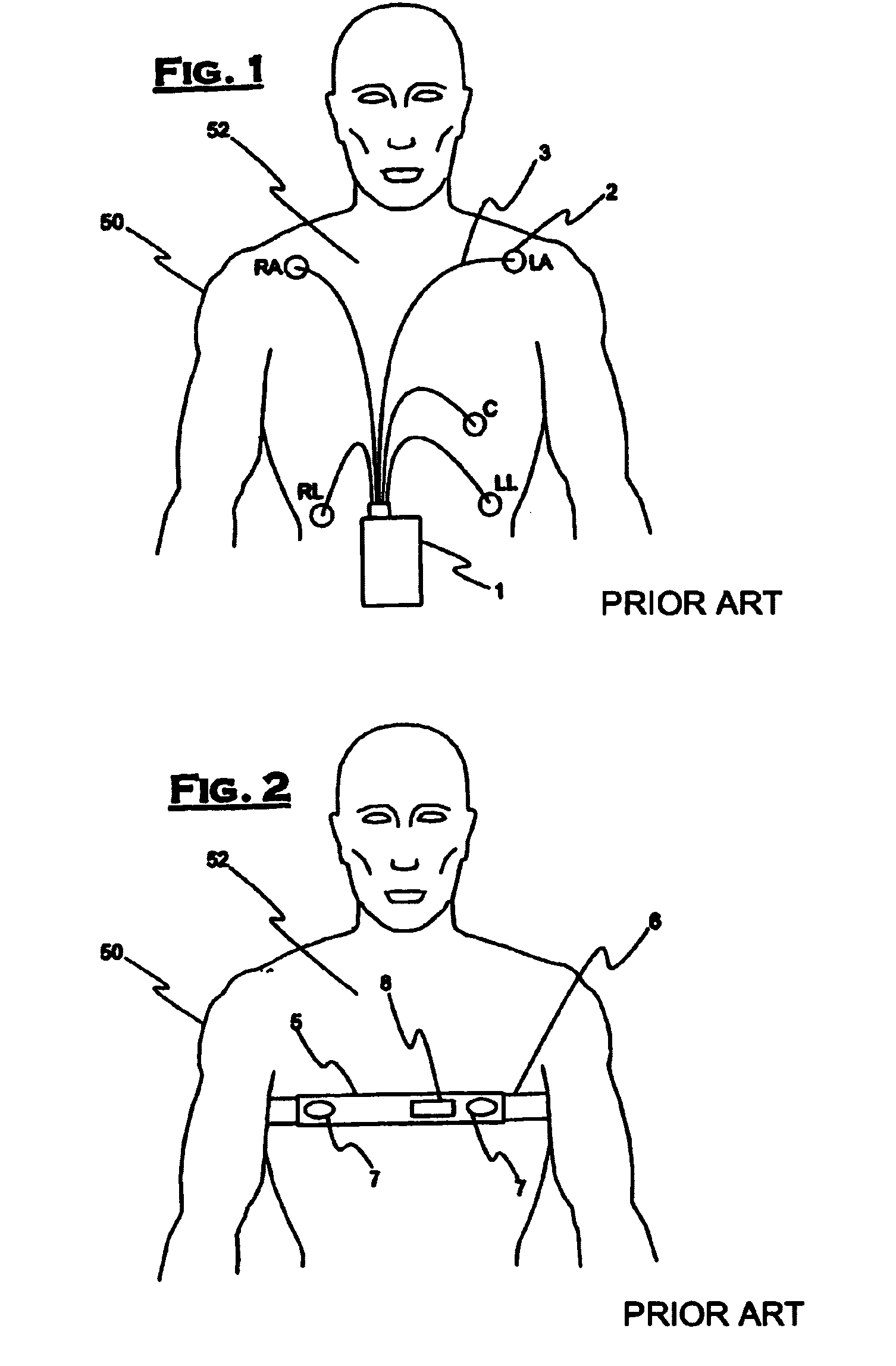
[0033]FIG. 1 illustrates a commonly used prior art clinical ambulatory ECG monitor connected to a chest 52 of a patient 50. Several leadwires 3 extend from a housing 1 to a plurality of electrodes 2 attached to chest 52. Electrodes 2 are labeled RA, LA, RL, C and LL. Housing 1 contains monitoring electronics and is generally supported by a sling (not shown in the figure) or arranged to be clipped to the patient's belt or the waistband of the patient's clothing. This support arrangement is objectionable due to the bulk and weight of the electronics and housing 1 and due to the often encountered difficulty of housing 1 falling loose from its support or attachment.

[0034]A rather aggressive adhesive is generally necessary to attach electrodes 2 because they must not only remain securely in contact with chest 52, but must also support the weight and possible tension of leadwires 3. The use of a strong adhesive results in considerable discomfort during removal of electrodes 2 and, in some...


PUM


Abstract

A medical monitor includes a lanyard and an electronic package supported in the manner of a pendant. The lanyard includes integral electrodes or other sensors for making physiological measurements, auxiliary components and connectors for electrically connecting the electrodes or sensors to the electronic package. The physiological measurements may be stored in the monitor for later readout, or may be transmitted, before or after processing, to a remote location.

Description

RELATED APPLICATIONS[0001]This applications is a continuation-in-Part of U.S. patent application Ser. No. 10 / 201075, filed on Jul. 23, 2002, herein incorporated by reference in its entirety, and claims the benefit of Provisional Application No. 60 / 308,070 filed on Jul. 26, 2001.BACKGROUND OF THE INVENTION[0002]1. Field of the Invention[0003]The invention relates to a medical monitoring device. More particularly, the invention relates to a patient-worn electronic monitoring device.[0004]2. Description of the Prior Art[0005]Modern medical practice makes extensive use of electronic vital signs monitoring. As technology has progressed, electronic monitoring devices have become more compact, easier to use, and have been made available to larger segments of the patient population. Today, most electronic monitors are what are termed “bedside monitors.” A bedside monitor consists of an electronics and display unit placed in close proximity to a patient bed. Cables connect the monitor to var...

Claims


Application Information

Patent Timeline
Patent Type & Authority Patents(United States)
IPC IPC(8): A61B5/00A61B5/332
CPCA61B5/0031A61B5/0404A61B5/1116A61B5/6822A61B5/6831A61B5/6833A61B5/6841A61B5/0002A61B5/6832A61B5/72A61B2562/227A61B2562/08A61B2560/04A61B2560/0468A61B5/0245A61B5/01A61B5/145A61B5/332A61B5/318
Inventor KINAST, ERIC
Owner DATASCOPE INVESTMENT
Why Eureka
Try Eureka