Method and apparatus for monitoring SF6 gas and electric utility apparatus

a technology of electric utility apparatus and gas monitoring method, which is applied in the direction of fluid tightness measurement, instruments, machines/engines, etc., can solve the problems of sf6 loss, several hundred thousand pounds of sf6 per year due to faulty seals, and loss of this expensive dielectric gas, etc., and achieves efficient forecasting

Inactive Publication Date: 2007-08-14
AVISTAR
View PDF7 Cites 16 Cited by
  • Summary
  • Abstract
  • Description
  • Claims
  • Application Information

AI Technical Summary

Benefits of technology

[0009]This invention uses the pressure and a calculated temperature of SF6 gas and calculates the number of moles present and corrects for changes in ambient condition in both the gas and its container. The number of moles n present in a fixed volume V is also a direct function of the pressure P and the temperature T of the gas. In this invention, there is collection of data and performance of a running calculation using a least squares fitting routine which is used to determine changes in molar content of the container. If the slope of the change of the molar content changes by a predetermined value, it is determined that a leak must be present. An alarm is then signaled electronically to an operator who monitors leak conditions when the predetermined value is exceeded. The trend average leak calculation allows for efficient forecasting for maintenance activities in the presence of slow SF6 leaks.

Problems solved by technology

Because of arcing considerations, and conditions inside the container, it is generally impractical to measure temperature of the gas directly inside of the container, especially in the case where it is desired to provide SF6 monitoring on an existing tank which does not include a provision for temperature measurement inside the tank.
In electric utilities, several hundred thousand pounds of SF6 per year are lost due to faulty seals.
The loss of this expensive dielectric gas is an environmental concern and is subject to routine pressure inspections to determine leakage.
Slow leaks from mechanical seals are difficult to detect and current technology in the electrical industries lack the requisite sensitivity.

Method used


Image

  • Method and apparatus for monitoring SF6 gas and electric utility apparatus
  • Method and apparatus for monitoring SF6 gas and electric utility apparatus
  • Method and apparatus for monitoring SF6 gas and electric utility apparatus

Examples


Embodiment Construction

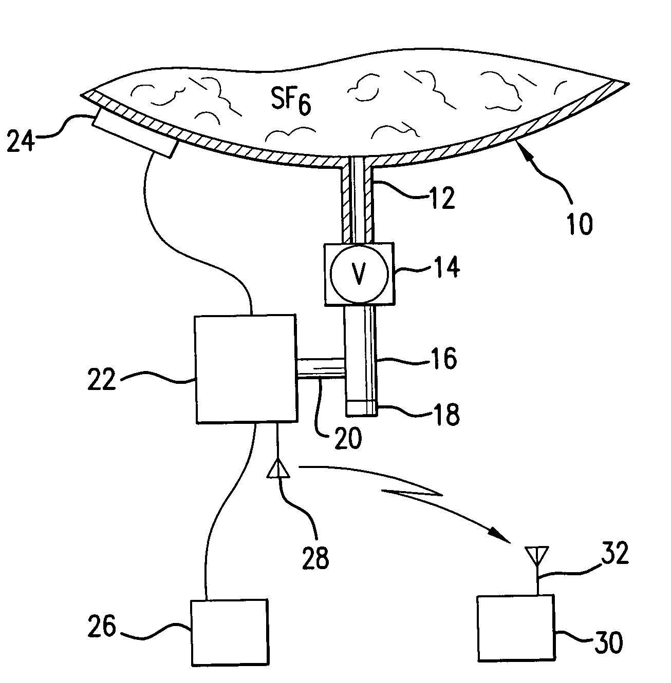
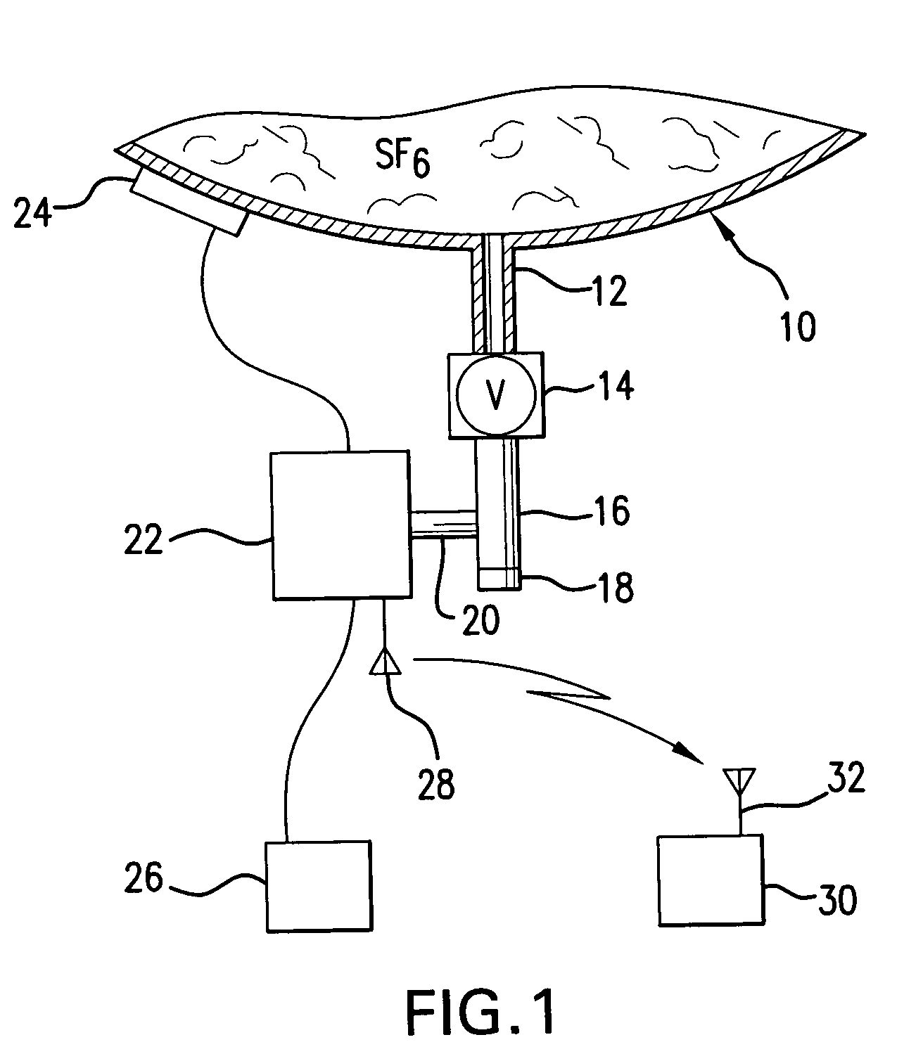
[0024]FIG. 1 shows a container (10) containing SF6 gas. Attached to the container is a service port (12) which is connected to a service valve (14). Service valve (14) is connected to a “T” pipe fitting (16). One end of the “T” pipe fitting (16) has a cap (18). Connected to the “T” fitting (16) is a nipple (20) which connects to a detector (22). The detector (22) also contains a radio board which sends unprocessed data to the gateway (30) by way of the transmitting antenna (28) and receiving antenna (32). The processor (computer) is contained in the gateway (30). Gateway (30) is a receiver, microprocessor (computer) and internet link located at a utility substation where a plurality of SF6 sensors are located. The microprocessor and associated memory collect data from all sensors located in the utility substation through antenna (32) and provide this data to the internet communication link for transmittal to a central monitoring location. The utility substation is normally not conti...


PUM


Abstract

A method for detecting loss of SF6 gas from electrical utility apparatus determines a molar ratio of gas in a container at an initial time and of gas in the container at a subsequent time. Measurement of temperature is determined by averaging ambient temperature and temperature of the surface of the container. The initial values of pressure and temperature define the initial value of n as follows:no=Pgas o / Tgas oThe value at a subsequent time isnn=Pgas n / Tgas nThe molar ratio can be defined asnn / no or as no / nn.

Description

RELATED APPLICATIONS[0001]This application is a continuation in part of Provisional Application 60 / 702,999 filed Jul. 7, 2005 and a continuation in part of Provisional Application 60 / 713,366 filed Sep. 2, 2005.FIELD OF THE INVENTION[0002]This invention relates generally to SF6 monitoring of containers or tanks for electrical apparatus used in power transmission. More particularly the invention relates to monitoring of SF6 gas in a tank containing electrical switching components.BACKGROUND OF THE INVENTION[0003]High voltage circuit breakers are used in the transmission and distribution of electrical energy. These circuit breakers are located inside of tanks which contain SF6 gas. The SF6 gas acts as an electrically insulating gas to prevent arcing. The purpose of the gas is to control arcing across electrical contacts during opening of closing of contacts in the breaker.[0004]SF6 gas monitors are known in the art as shown in U.S. Pat. No. 4,489,592 Pacanowski et al., U.S. Pat. No. 4,...

Claims


Application Information

Patent Timeline
Patent Type & Authority Patents(United States)
IPC IPC(8): G01F17/00
CPCG01M3/3236G01M3/3272H01H33/563H02B13/0655G01N33/0036
Inventor RHODES, GEORGE W.MIGLIORI, ALBERTFIN, TRISTANWILLARD, STEVEN FRANK
Owner AVISTAR
Why Eureka
Try Eureka