Apparatus for removing the tips of tablet punches

a tablet punch and apparatus technology, applied in the field of apparatus for destroying tablets, can solve the problems of frequent replacement before they are worn, inconvenient replacement, and eventually wear of the tablets discussed above, and achieve the effect of safe and efficient replacemen

Inactive Publication Date: 2007-08-21
STEVENS PHARMA EQUIP INDS
View PDF13 Cites 8 Cited by
  • Summary
  • Abstract
  • Description
  • Claims
  • Application Information

AI Technical Summary

Benefits of technology

[0008]It is another object of the present invention to provide a safe and efficient process for cutting off the tips of tablet punches before they are disposed of.

Problems solved by technology

The punches discussed above eventually do wear out and must be replaced.
Furthermore, they are frequently replaced before they are worn when a particular medication is no longer being produced or when it is desired to change the indicia on the tablets.
However, there are many problems, disadvantages, and safety issues involved in this procedure.
Primarily, it is a time-consuming and tedious process as only one punch may be worked on at a time.
There is also the possibility that the indicia may not be totally removed and that the punch is then reused.
Even further, there is always the danger of injury to the worker who is manually grinding the tips with the grinding wheel.

Method used


Image

  • Apparatus for removing the tips of tablet punches
  • Apparatus for removing the tips of tablet punches
  • Apparatus for removing the tips of tablet punches

Examples


Embodiment Construction

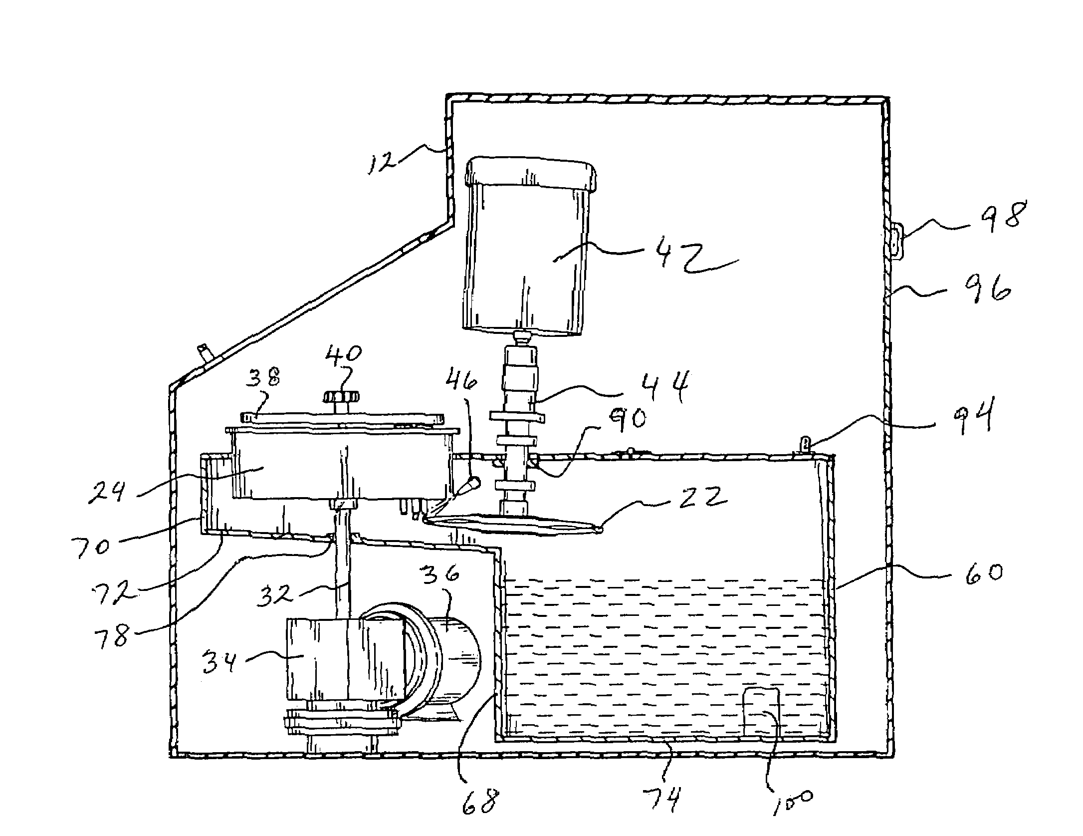
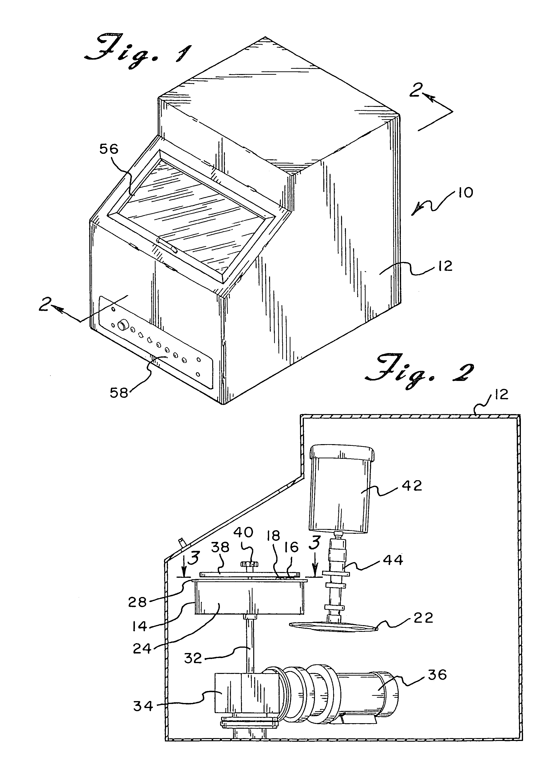
[0026]Referring now to the drawings in detail wherein like reference numerals have been used throughout the various figures to designate like elements, there is shown in FIG. 1 an apparatus constructed in accordance with the principles of the present invention and designated generally as 10.

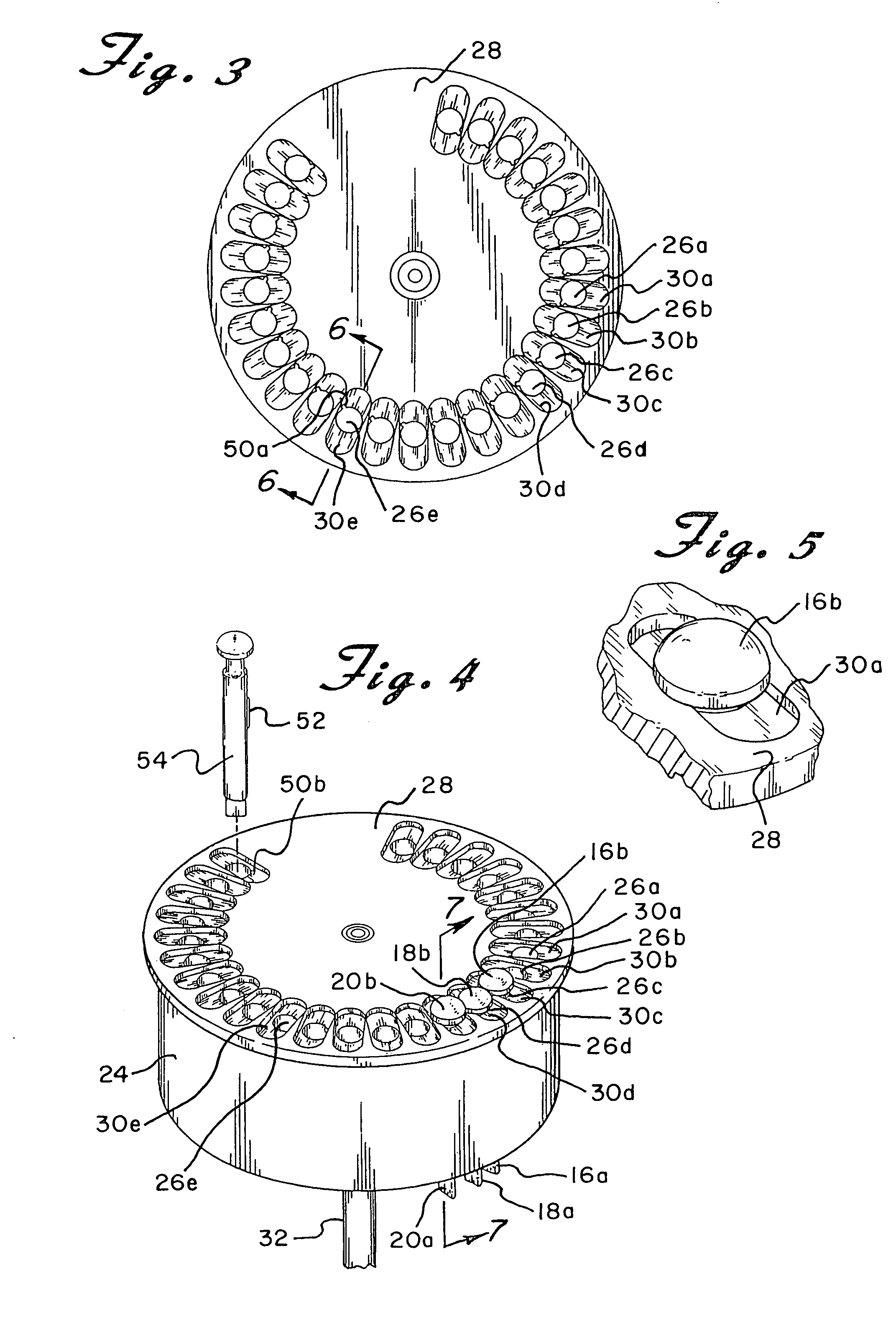
[0027]The apparatus of the present invention essentially includes a housing 12 which contains therein all of the operative devices for performing the required cutting operation. More particularly, mounted within the housing 12 is a means 14 for supporting or holding a plurality of tablet punches 16, 18, and 20 for example, and a cutting wheel or disc 22. The supporting means 14 may be a turret comprised of a drum 24 and a plurality of substantially vertically aligned circular holes, 26a-26e for example, around the periphery thereof. (See FIG. 3.) The drum 24 may be approximately four inches thick. Each of the holes is adapted to support a punch in a substantially vertical orientation so that the ...


PUM

PropertyMeasurementUnit
angleaaaaaaaaaa
thickaaaaaaaaaa
diameteraaaaaaaaaa

Abstract

A machine for removing the tips of tablet punches includes a housing that contains a turret that is rotated about a substantially vertical axis and a cutting wheel. The turret supports a plurality of tablet punches in a substantially vertical position with the tips of the punches being exposed below the turret. A cutting wheel is positioned below the turret and is located in a position so as to be in the path of the tips as the turret rotates. A motor rotates the cutting wheel so that the tips are removed from the punches as they are rotated into the path of the wheel. A nozzle is directed to the position where the cutting wheel engages the tips of the punches and sprays a cooling fluid in order to cool the cutting wheel and tips to prevent overheating thereof.

Description

CROSS REFERENCE TO RELATED APPLICATION[0001]This application is a Continuation-in-Part of prior U.S. application Ser. No. 10 / 122,260, filed Apr. 12, 2002, now U.S. Pat. No. 6,857,346.BACKGROUND OF THE INVENTION[0002]The present invention is directed toward an apparatus for destroying a tablet punch and more particularly, toward a machine with a cutting wheel that removes the tip of a tablet punch.[0003]Tablets for use as drugs and for other pharmaceutical purposes are typically made by depositing a quantity of the medicinal powder into a die and compressing the powder. This is accomplished by lowering and raising a pair of punches onto the powdered material in the die. The punches are located on turrets that rotate about their respective vertical axis. Some punches have a recessed end portion so that the tablet will have a domed or beveled surface. The recessed portion of one or both of the punches frequently has some type of marking such as a letters, numbers, logos or other indici...

Claims


Application Information

Patent Timeline
Patent Type & Authority Patents(United States)
IPC IPC(8): B26D1/143B26D7/08
CPCB26D7/088Y10T83/9403Y10T83/242Y10T83/293Y10T83/6552Y10T83/263
Inventor MCLEAN, STEVEN
Owner STEVENS PHARMA EQUIP INDS
Why Eureka
Try Eureka