Liquid crystal display

a liquid crystal display and display unit technology, applied in the field of liquid crystal display, can solve the problems of difficult adjustment or position inconvenient manual adjustment of the position or the angle of the display unit, etc., and achieve the effect of easy lifting of the display uni

Active Publication Date: 2007-08-21
QUISDA CORP +1
View PDF12 Cites 30 Cited by
  • Summary
  • Abstract
  • Description
  • Claims
  • Application Information

AI Technical Summary

Benefits of technology

[0014]Accordingly, an object of the invention is to provide a pre-force mechanism

Problems solved by technology

However, the display unit 1 becomes difficult to adjust or position at a predetermined height or angle from the nut 222 on the

Method used


Image

  • Liquid crystal display
  • Liquid crystal display
  • Liquid crystal display

Examples


Embodiment Construction

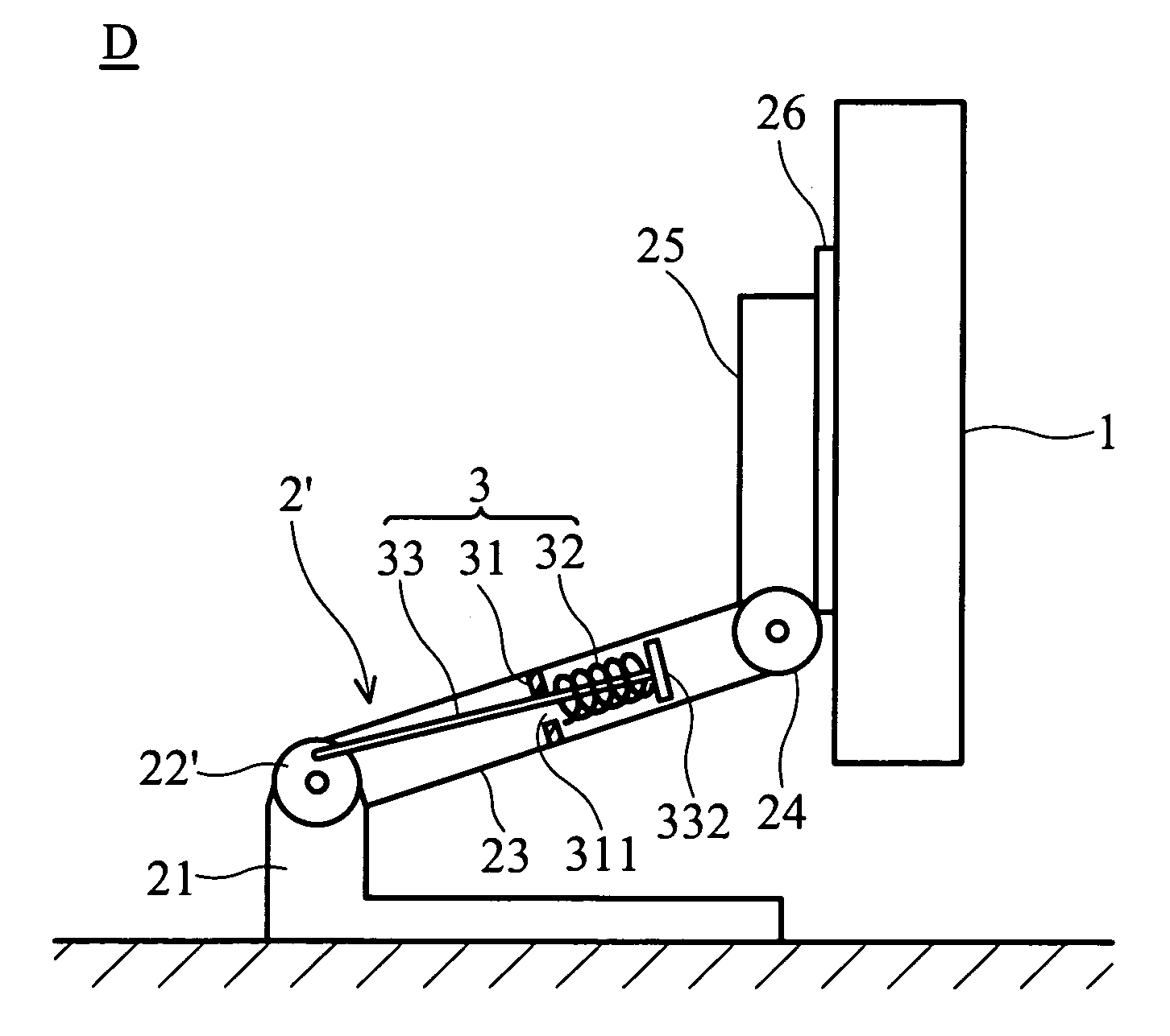
[0034]As shown in FIG. 6, when the liquid crystal display is situated in a stable condition, the present invention provides a pre-force mechanism 3 (as FIG. 8) to generate a second torque TP in a pivot of a liquid crystal display (LCD) in advance, such that the second torque TP is formed to overcome a first torque TW generated by the weight of the display unit 1. The direction of the first torque TW is opposite to that of the second torque TP. In addition, a third torque is exerted on the pivot of the LCD because of the frictional force within the pivot. When the LCD is situated in the stable condition, the first torque TW generated by the weight of the display unit 1 is larger than the second torque TP formed by the pre-force mechanism 3 and the third torque TF3 formed by the frictional force, that is, TW≧TF3+TP. Because of the second torque TP, the third torque TF3, the frictional torque for balancing the weight of the display unit 1, can be reduced. That is to say, the frictional...


PUM


Abstract

A liquid crystal display having a supporting base, a display unit and a pre-force mechanism. The supporting base has at least one pivot and at least two sections joined thereby, and the display unit is connected to the supporting base, exerts a first torque on the pivot by the weight of the display unit. The pre-force mechanism is connected to the pivot and exerts a second torque on the pivot. The first torque is opposite to the second torque.

Description

BACKGROUND OF THE INVENTION[0001]1. Field of the Invention[0002]The present invention relates to a liquid crystal display, and in particular to a liquid crystal display with a supporting base.[0003]2. Description of the Related Art[0004]In FIG. 1, a conventional liquid crystal display on a surface 5 is situated in a stable condition. W is the weight of the display unit 1, and F is external force used for lifting up the display unit 1. The force F is directly on the display unit 1 and rotated the first pivot 22 in a counterclockwise direction.[0005]The liquid crystal display has a display unit 1 and a supporting base 2. The supporting base 2 has a first section 21, a first pivot 22, a second section 23, a second pivot 24, a third section 25 and a plate 26. The first pivot 22 and the second pivot 24 have the same structure, and the first pivot 22 connects the first section 21 and the second section 23, and the second pivot 24 connects the second section 23 and the third section 25. Th...

Claims


Application Information

Patent Timeline
IPC IPC(8): A47F5/12G02F1/133G02F1/1333
CPCF16M11/04F16M11/10F16M11/38F16M11/2021Y10S248/923F16M2200/044
Inventor YEN, CHING-HUICHIU, POSEN
Owner QUISDA CORP
Why Eureka
Try Eureka