Vehicular rear suspension system

a rear suspension and vehicle technology, applied in the direction of resilient suspensions, interconnection systems, vehicle components, etc., can solve problems such as degradation of steering stability, and achieve the effect of enhancing steering stability and lateral rigidity of the ground contact point of the rear wheel

Inactive Publication Date: 2007-08-21
HONDA MOTOR CO LTD
View PDF20 Cites 65 Cited by
  • Summary
  • Abstract
  • Description
  • Claims
  • Application Information

AI Technical Summary

Benefits of technology

[0011]With the arrangement of the first aspect, the straight line passing through the first joint connecting the knuckle to the first lateral arm which is disposed at the highest position relative to all three lateral arms, and the second joint connecting the knuckle to the second lateral arm, which, relative to the other two lateral arms, is positioned on the forward side of the vehicle body, intersects the road surface at the intersection point located behind the ground contact point of the rear wheel in the longitudinal direction of the vehicle body. The longitudinal elastic coefficients of the first, second, and third lateral arms are set in a predetermined relationship. Therefore, the intersection point at which the elastic kingpin intersects the road surface is accurately positioned toward the rear of the vehicle body relative to a point of action of a lateral force when turning. As such, a lateral toe-in force is reliably achieved while the steering stability of the vehicle is enhanced. Moreover, because of the above-mentioned arrangement for the first, second and third lateral arms, the lateral toe-in force is achieved without decreasing the elastic coefficient of the second lateral arm, which is at a relatively low position, wherein the lateral rigidity of the ground contact point of the rear wheel is enhanced.

Problems solved by technology

Furthermore, when a lateral force acts from the road surface on a rear wheel during turning of the vehicle, rear wheel toe-out occurs, leading to a degradation in steering stability.

Method used


Image

  • Vehicular rear suspension system
  • Vehicular rear suspension system
  • Vehicular rear suspension system

Examples


Embodiment Construction

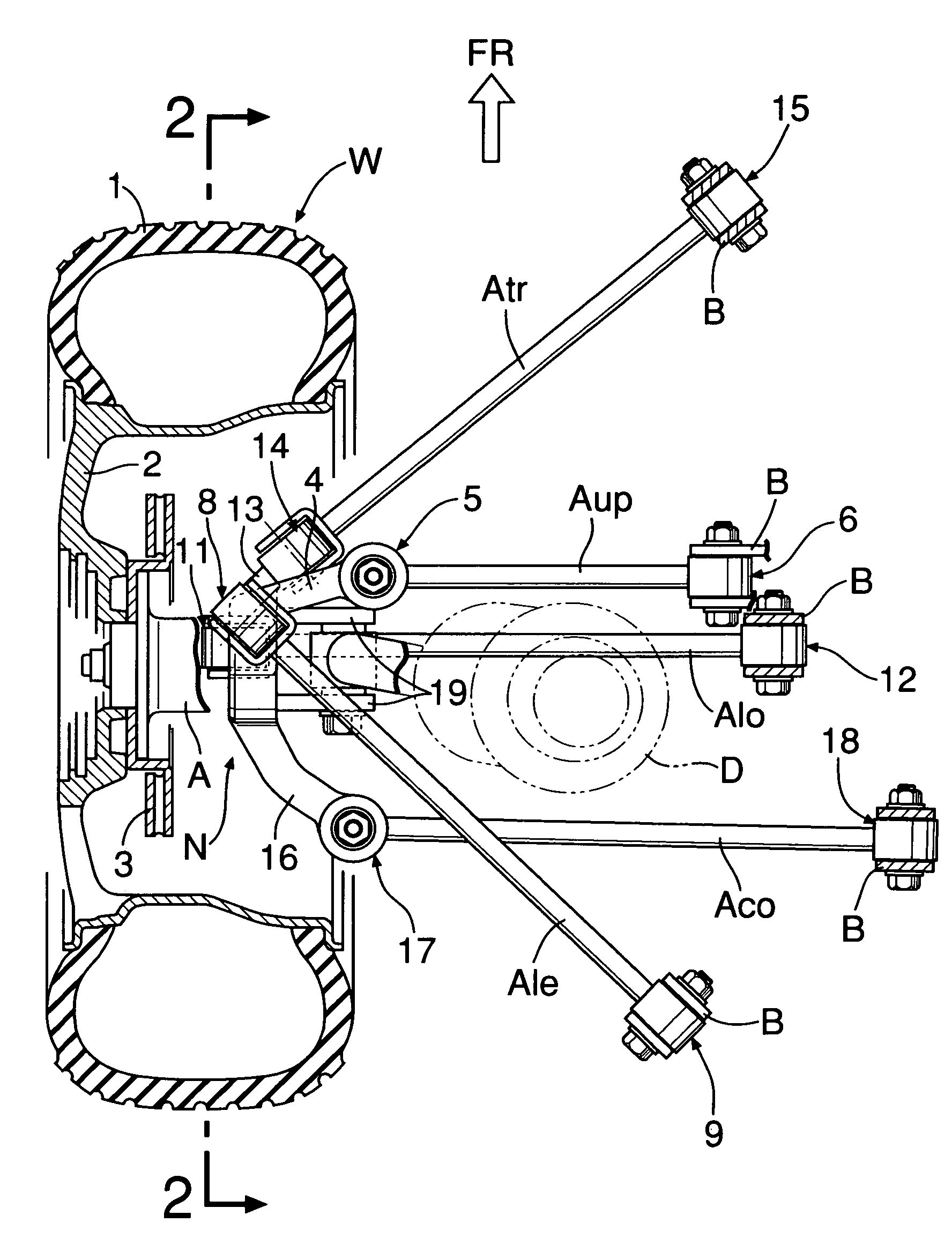
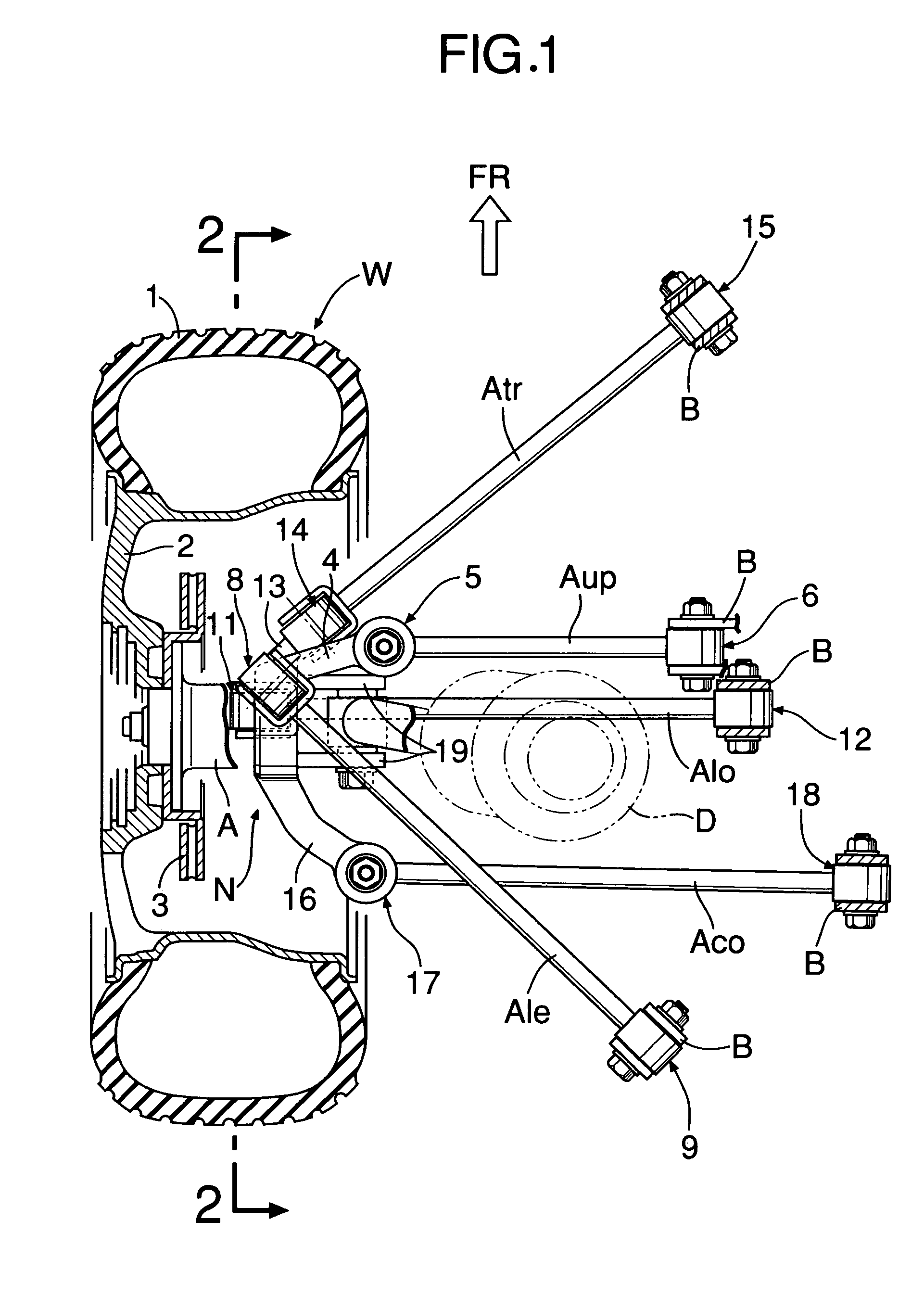
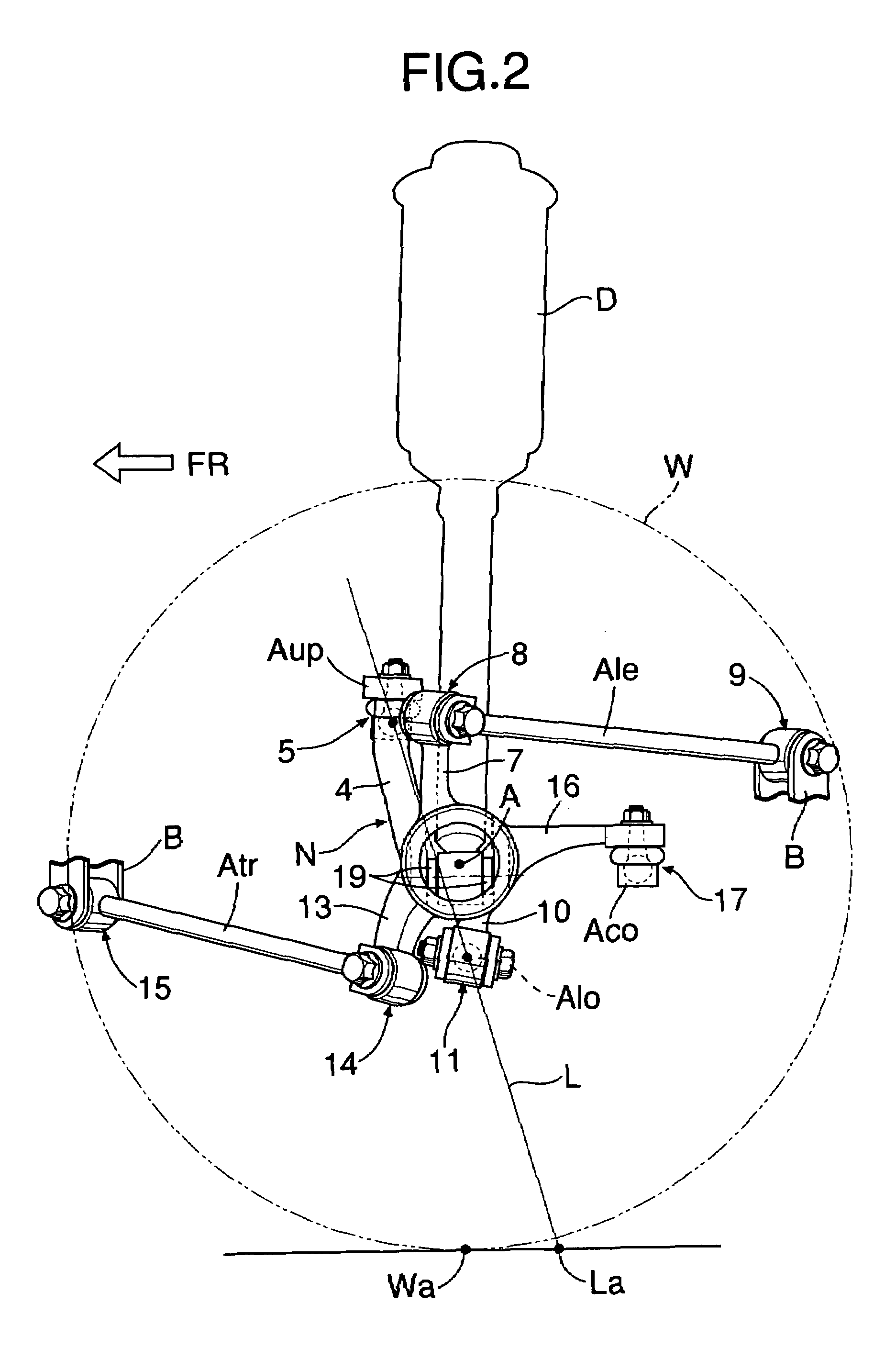
[0019]FIG. 1 and FIG. 2 show a multi-link suspension system for a rear wheel W on the left side of a front-wheel-drive vehicle. The rear wheel W, which includes a tire 1, a wheel body 2, and a brake disk 3, is rotatably supported by a knuckle N via an axle A. The outer and inner ends of an upper arm Aup are connected, respectively, to an upper arm mount 4 projecting upward from the knuckle N and a vehicle body B via a ball joint 5 and a rubber bushing joint 6. The outer and inner ends of a leading arm Ale are connected, respectively, to a leading arm mount 7 projecting upward from the knuckle N and the vehicle body B via rubber bushing joints 8 and 9. The upper arm Aup and the leading arm Ale are positioned in substantially the same horizontal plane above the axle A. The upper arm Aup extends in the lateral direction of the vehicle body. The leading arm Ale extends from the rear inner side of the vehicle body to the front outer side of the vehicle body.

[0020]The outer and inner ends...


PUM


Abstract

A vehicular rear suspension system includes an upper arm, a lower arm, and a control arm, each of which is connected to a knuckle. A straight line passing through a ball joint and a rubber bushing joint intersects the road surface at an intersection point that is positioned behind a ground contact point of the rear wheel in the longitudinal direction of the vehicle body. The ball joint connects the upper arm to the knuckle, and the rubber bushing joint connects the lower arm to the knuckle. Longitudinal elastic coefficients of the three arms are set in a predetermined relationship. Therefore, the intersection point at which an elastic kingpin intersects the road surface is positioned without fail behind a point of action of a lateral force when turning in the longitudinal direction of the vehicle body to achieve a lateral force toe-in and enhanced steering stability of the vehicle.

Description

RELATED APPLICATION DATA[0001]The present invention is based upon Japanese priority application No. 2004-36608, which is hereby incorporated in its entirety herein by reference.BACKGROUND OF THE INVENTION[0002]1. Field of the Invention[0003]The present invention relates to a vehicular rear suspension system which includes a knuckle rotatably supporting a rear wheel via an axle, a trailing arm extending from a joint on a vehicle body in the longitudinal direction of the vehicle body and connected to the knuckle, and three lateral arms extending from joints on the vehicle body in the lateral direction of the vehicle body and connected to the knuckle.[0004]2. Description of the Related Art[0005]Japanese Patent Application Laid-open No. 7-186649 discloses a multi-link suspension system which includes a trailing arm, a leading arm, an upper arm, a lower arm, and a control arm.[0006]In the known multi-link suspension system, high caster rigidity and high longitudinal compliance are achiev...

Claims


Application Information

Patent Timeline
Patent Type & Authority Patents(United States)
IPC IPC(8): B60G3/04B60G3/18B60G3/20
CPCB60G3/20B60G2200/156B60G2200/184
Inventor AMANO, HIDETOSHI
Owner HONDA MOTOR CO LTD
Why Eureka
Try Eureka