Tire track

a technology of flexible track and tire, applied in the direction of wheel attachment, mechanical equipment, transportation and packaging, etc., can solve the problems of insufficient traction provided by the cams positioned between the adjacent tires, decreased tension during use of the track, and complicated operation and time-consuming, so as to reduce the risk of vibration

Inactive Publication Date: 2007-08-21
MICHELIN & CO CIE GEN DES ESTAB MICHELIN
View PDF20 Cites 9 Cited by
  • Summary
  • Abstract
  • Description
  • Claims
  • Application Information

AI Technical Summary

Benefits of technology

[0010]There is thus a need to a track which is suitable for converting a wheeled vehicle into a tracked vehicle, which is removable mountable to the wheels of the vehicle, in which there is optimum transfer of driving or traction forces between the wheels and the track independent of the life time of the track or vehicle or the time the track has been used with the vehicle, and which shows a reduced risk to the occurrence of vibrations.

Problems solved by technology

This operation is complicated and time consuming.
However, tension has been found to decrease during use of the track.
Besides this, the traction provided by the cams positioned between the adjacent tires appears to be insufficient, slipping at the front side of the vehicle being the result.
However, the ability of the track to deform in longitudinal direction and to adapt itself to varying dimensions of the wheels is limited, thus leading to poor circumferential traction.
Besides this, the track shows a serious risk to slipping at large powers in which case there is no engagement of the protrusions and no driving of the track.
Also the track is subject to vibrations as the inwardly projections engage between the ribs.
The track disclosed in U.S. Pat. No. 3,161,443 is not suitable for use with small wheels as in that case the number of contact points between the track and wheels is insufficient.

Method used


Image

  • Tire track
  • Tire track
  • Tire track

Examples


Embodiment Construction

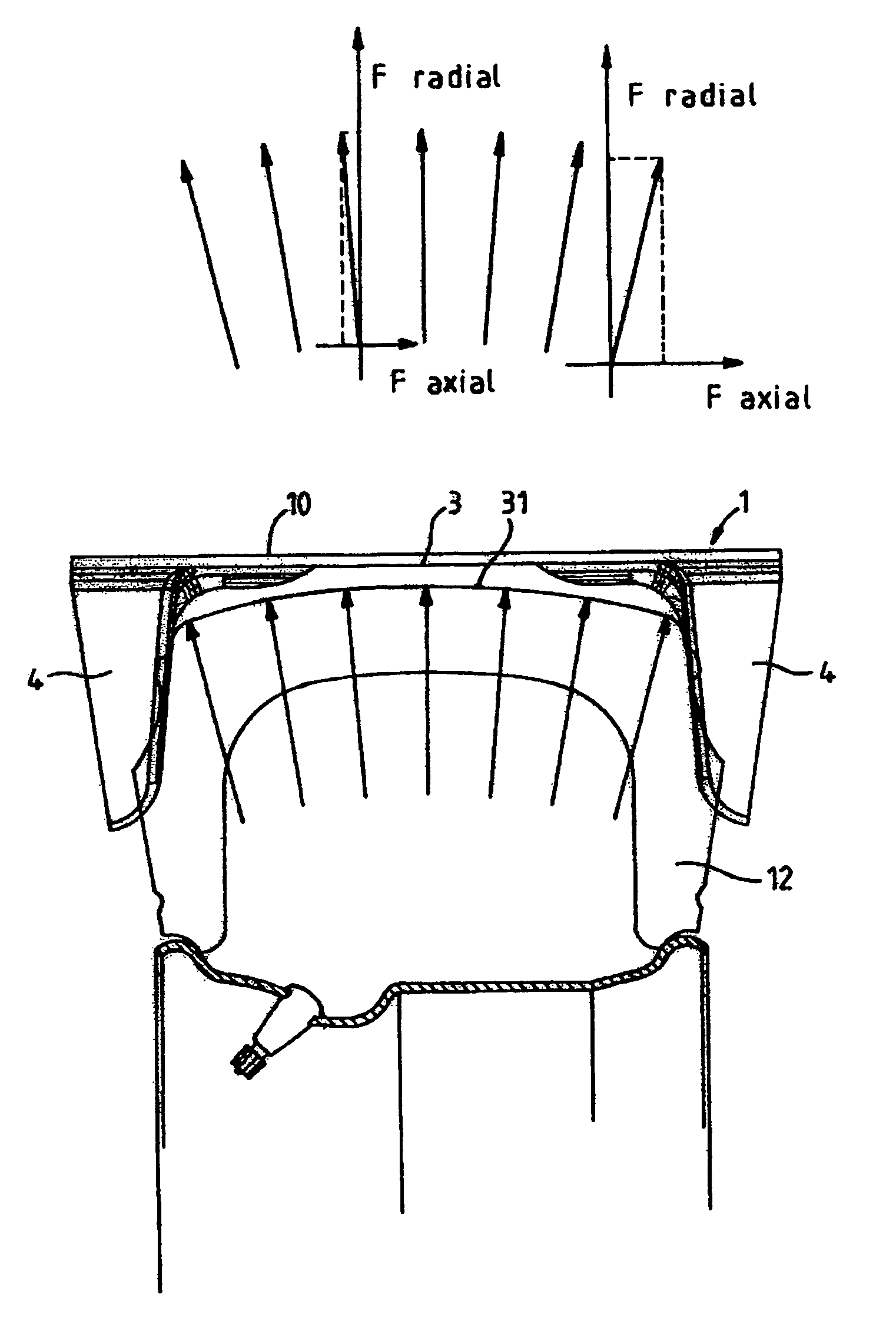
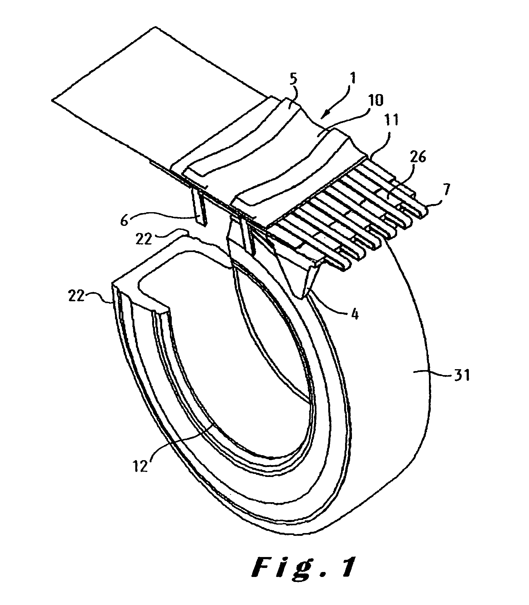
[0060]Referring to FIG. 1, there is shown a portion of a flexible track 1 according to the invention, mounted to a tire-wheel assembly 12 of a wheeled vehicle (not shown). The track 1 comprises a band 5, the band being made of a flexible material. The band 5 may be made of any suitable flexible material known to the person skilled in the art, but is preferably made of a plastic material, preferably an elastomeric material.

[0061]As is shown in more detail in FIGS. 4, 5a and 5b, 7, 8a, 8b and 9, the track 1, in particular the band 5 comprises an inner circumferential surface 3 running along the circumference of the band, the inner surface 3 forming a contact surface between the band 5 or track 1 and the tire-wheel assembly 12 and providing a running surface for the wheels 12. The inner surface 3 is provided to contact the running surface 31 of the tires. The track 1, in particular the band 5 also comprises an outer circumferential surface 10, which is provided to contact the medium ov...


PUM


Abstract

A unitary flexible track for converting a wheeled vehicle into a tracked vehicle, the track being provided for mounting in longitudinal direction around at least two successive vehicle tire-wheel assemblies in movement direction of the vehicle, the track having an inner circumferential track surface provided to form a running surface for the wheels and an outer circumferential surface provided to form a running surface for the track with respect to the medium over which the track is to be displaced, each tire-wheel assembly having a circumferential running surface provided to contact the inner circumferential track surface of the track, each tire-wheel assembly comprising a loaded wheel part and a non-loaded wheel part. The track comprises a plurality of spaced apart guiding wings disposed along opposite longitudinal sides of the track and protruding inwardly from the inner surface of the track so as to form on the track an inner circumferential channel for receiving the tire-wheel assemblies, the guiding wings engaging opposite lateral sides of the loaded part of the tire-wheel assembly and to exert a clamping force thereto in cross direction of the track and the tire-wheel assembly to transfer a driving force between the tire-wheel assembly and the track, opposite guiding wings being positioned at a distance from each other which is smaller than the width of the tire-wheel assembly when loaded and which is larger than the width of the tire-wheel assembly when not loaded.

Description

CROSS-REFERENCE TO RELATED APPLICATIONS / INCORPORATION BY REFERENCE[0001]This application is a continuation-in-part of U.S. patent application Ser. No. 10 / 615,070, filed on Jul. 8, 2003 now abandoned, which claims the priority benefits of European Patent Application No. 02447130.2, filed on Jul. 10, 2002.FIELD OF THE INVENTION[0002]The present invention relates to a monolithic flexible track for converting a wheeled vehicle into a tracked vehicle as disclosed in the preamble of the first claim. The term monolithic is used herein as opposed to a track composed of a plurality of connected rigid elements extending in cross direction of the length of the track, wherein the rigid elements may be embedded in a rubber phase or not.BACKGROUND[0003]In the past, a vast number of solutions have been proposed for converting a wheeled vehicle into a tracked vehicle. According to one of these solutions a monolithic flexible track is installed around a pair of wheels remote from each other on the s...

Claims


Application Information

Patent Timeline
Patent Type & Authority Patents(United States)
IPC IPC(8): B62D55/04B62D55/253B62D55/24
CPCB62D55/244
Inventor PRINGIERS, KOENRAAD
Owner MICHELIN & CO CIE GEN DES ESTAB MICHELIN
Why Eureka
Try Eureka