Surgical scrub brush and cleaner apparatus

a scrub brush and scrub brush technology, applied in the field of scrub brushes, can solve the problems of ineffective cleaning process, less effective treatment, and unsubstantially modified scrub brushes used by medical professionals for quite some time, and achieve the effect of time-saving and efficien

Active Publication Date: 2007-08-28
BIOMED PACKAGING SYST
View PDF16 Cites 16 Cited by
  • Summary
  • Abstract
  • Description
  • Claims
  • Application Information

AI Technical Summary

Benefits of technology

[0013]Upon applying an insignificant or minor amount of manipulative force to the base of the inventive brush-sponge, the professional is then able to bring opposing sidewalls of the sponge towards one another and, depending on the outer dimensions of the instrument, practically surround the entire periphery of the instrument's body by the sponge. Finally, displacing the brush-sponge and instrument relative to one another, the professional can treat the surface of the instrument in a time-effective and efficient manner.
[0014]As is known, the sponge may be used for numerous purposes including, for example, cleaning the hands of the professional, treating cuts and wounds and, as discussed above, sterilizing instruments. Depending on the particular application, the surface of the sponge may be relatively smooth, which is particularly important while treating the patient's open wounds, or relatively rough, which may be advantageous for cleaning the instruments.
[0016]In addition to the smoothness of the surface, a relatively high PPI improves the capacity of the sponges to distribute treating fluid numerous times (meaning the high PPI sponge retains a lot of fluid and produces suds easily), but a high PPI also reduces the volume of the delivered fluid. In contrast, sponges with a relatively low PPI, for example a PPI from 10 to 60, delivers a greater volume of liquid-fluid at once, but thereafter becomes dry rather quickly. In other words, the low PPI sponge suds easily but also releases a higher volume of washing / cleaning / sterilizing fluid to carry away released debris.
[0018]To facilitate bending of the base in either direction (for scrubbing or sponge usage), which causes the sidewalls of the base to approach one another in either direction, the base of the inventive scrub brush-sponge has a plurality of attenuated hinge regions provided along the edges of the base so as to minimize bending and twisting resistance to the applied force. Alternatively or, preferably, in combination with the hinge regions, the edges or corner of the base are recessed to even further increase the flexibility of the base. In an additional embodiment, both the edges of the base and the base floor itself may be provided with cut-lines, or cut out portions, that act as slip plains and allow sections of the base edge to move relative to one another or that allow a floor of the base to shift relative to an adjacent the base edge portion.

Problems solved by technology

While a minor amount of brush modification continues, surprisingly, scrub brushes used by medical professionals have not been substantially modified for quite some time.
While such rectangular sponges may effectively clean flat surfaces, they may be less effective while treating annular surfaces, which are rather typical for a great variety of medical instruments.
However, as mentioned above, many instruments can be reused during the same medical procedure and, thus, have to be repeatedly cleaned before each subsequent use.
Since the base of the typical brush may not be sufficiently flexible, the user has to apply excessive bending forces to flex the base so that the sponge would surround the annular body of the medical instrument.
Otherwise, without flexing the base, a typical rectangular sponge may clean only a segment of the entire annular body, which leads to a time-ineffective cleaning process in a situation often requiring the instantaneous availability of any given instrument.
Assuming that the user does not experience any difficulty in flexing the scrub brush-sponge for cleaning medical instruments, the scrub still may remain inefficient, because the surface of the sponge is typically smooth.
And while a typical smooth surface is perhaps pleasant for cleaning the user's hands, it may be ineffective for cleaning the metallic or other surfaces of medical instruments.

Method used


Image

  • Surgical scrub brush and cleaner apparatus
  • Surgical scrub brush and cleaner apparatus
  • Surgical scrub brush and cleaner apparatus

Examples


Embodiment Construction

[0025]Reference will now be made in detail to several embodiments of the invention that are illustrated in the accompanying drawings. Wherever possible, same or similar reference numerals are used in the drawings and the description to refer to the same or like parts or steps. The drawings are in simplified form and are not to precise scale. For purposes of convenience and clarity only, directional terms, such as top, bottom, up, down, over, above, and below may be used with respect to the drawings. These and similar directional terms should not be construed to limit the scope of the invention in any manner. The words “connect,”“couple,” and similar terms with their inflectional morphemes do not necessarily denote direct and immediate connections, but also include connections through mediate elements or devices.

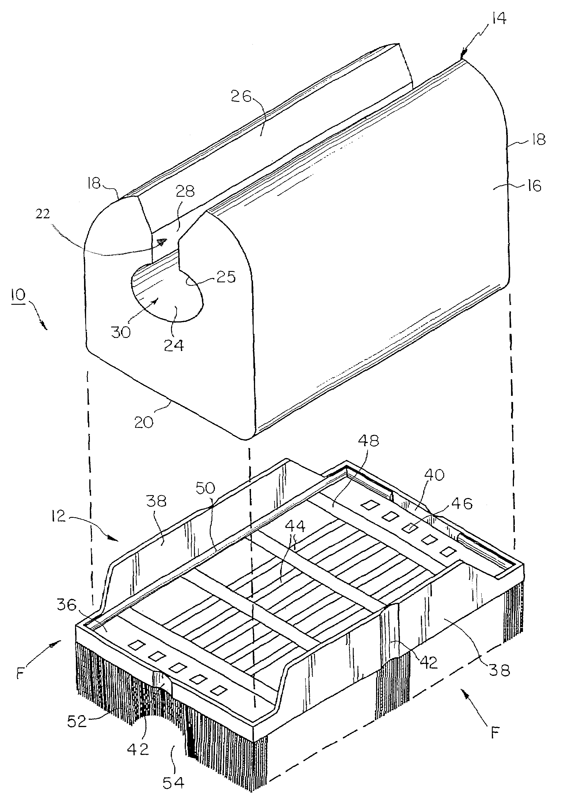
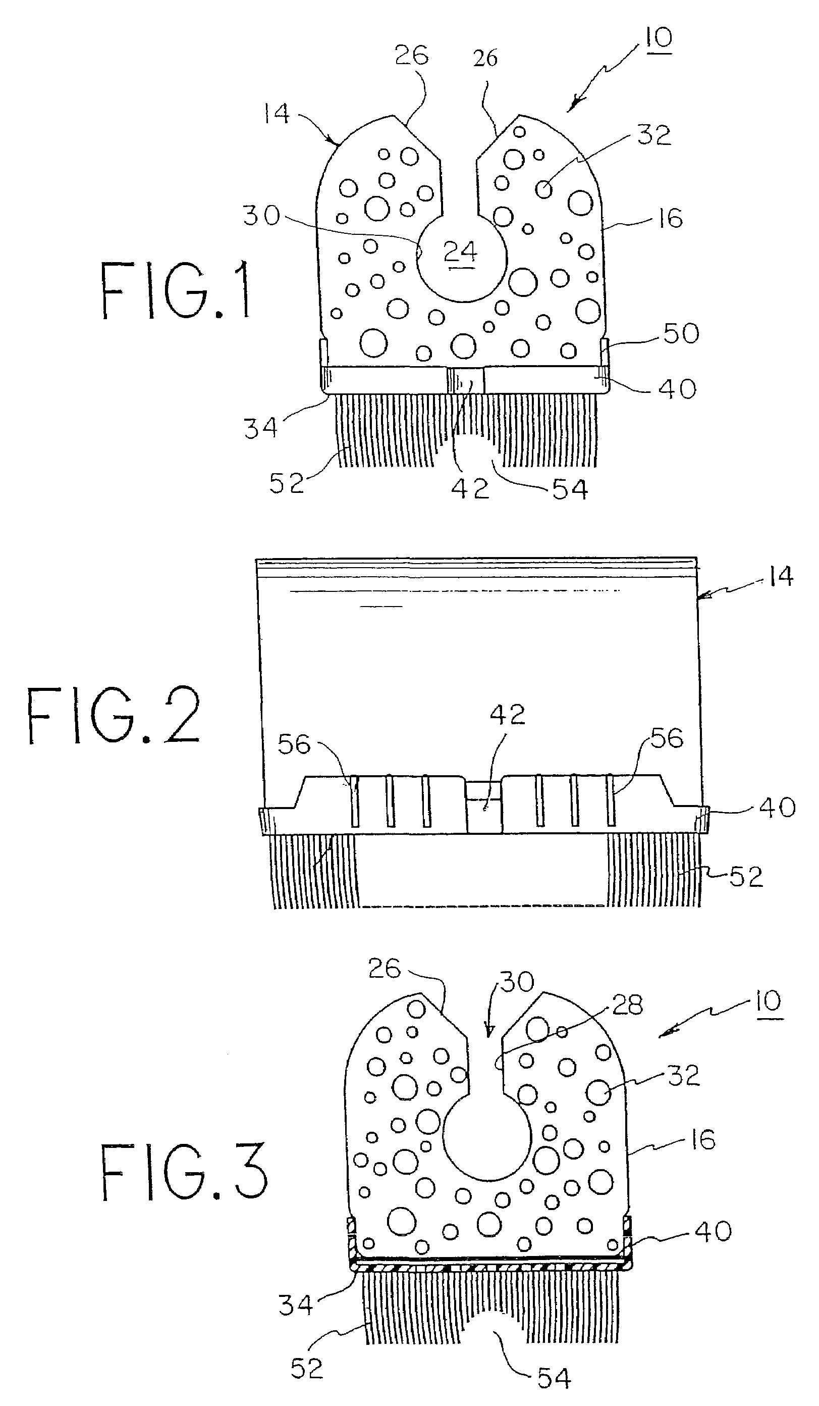
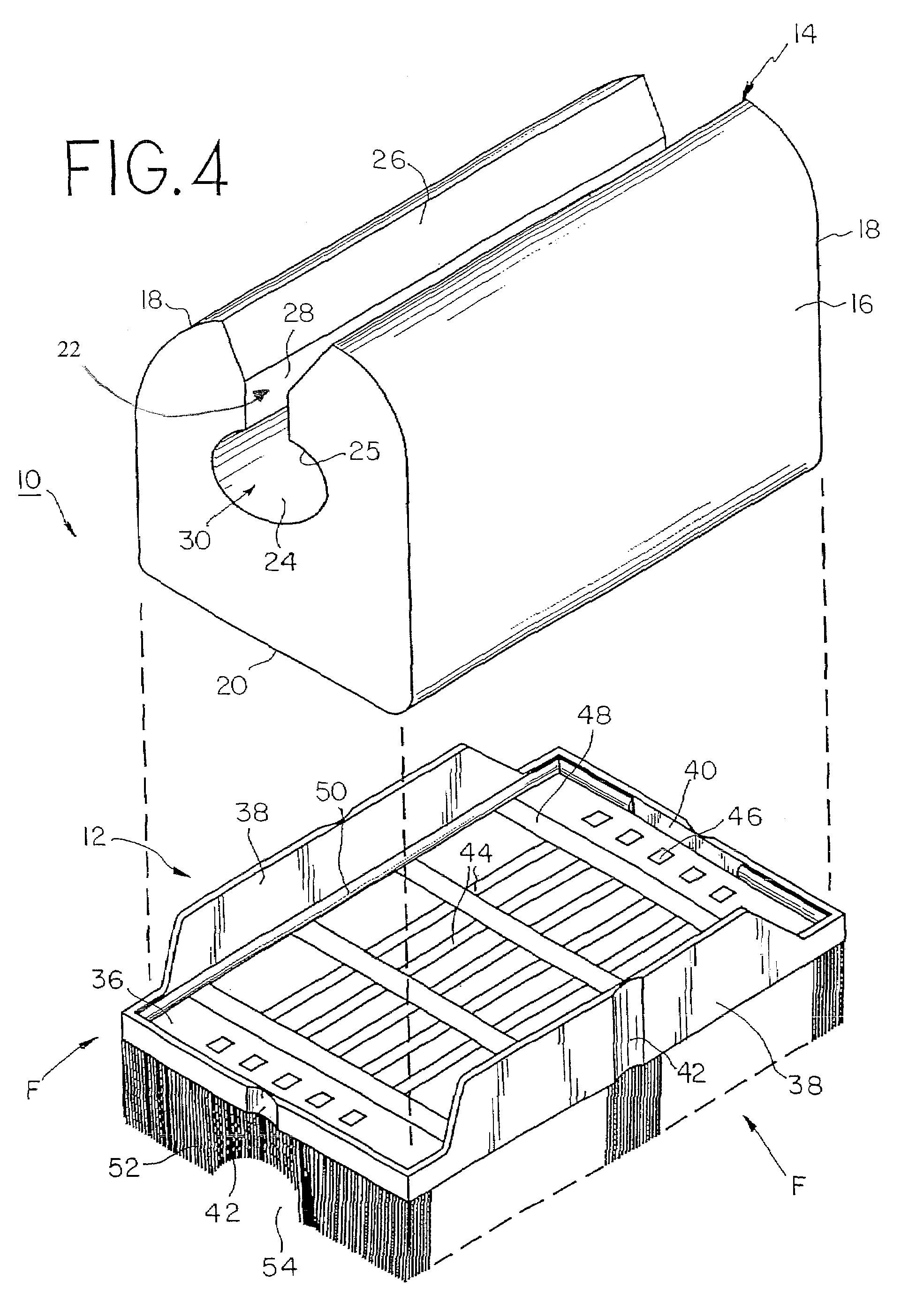
[0026]FIGS. 1, 3 and 4 illustrate a scrub brush-sponge 10, which is configured to provide a treatment of an annular body of a medical instrument that can be used more than on...


PUM


Abstract

A scrub brush-sponge includes a base provided with a recessed peripheral lip, which has a plurality of attenuated regions configured to minimize the resistance of the base to external bending forces, and a sponge coupled to the base and made from polymeric material, which may have as low a PPI as 10. The sponge is configured so that it can effectively surround at least a substantial peripheral portion of instruments or portions to be treated with fluid, which is contained within the sponge, without applying substantial external forces to the base.

Description

BACKGROUND OF THE INVENTION[0001]1. Field of the Invention[0002]The present invention relates to scrub sponges, and particularly, relates to scrub brush-sponges associated with a variety of medical procedures and adaptable for treating medical instruments.[0003]2. Description of the Related Art[0004]Numerous brush structures are known in the art. Some of these structures are functionally effective as well as convenient in use or ergonomic. While a minor amount of brush modification continues, surprisingly, scrub brushes used by medical professionals have not been substantially modified for quite some time. Structurally, a typical scrub brush has a base coupled to a rectangular sponge, which is saturated with antiseptic, germicide and / or soapy fluid and has a generally rectangular cross-sectional shape.[0005]In the medical field, many scrub brush-sponges have a great variety of adaptations. Besides traditional functions, such as cleaning the hands of the professional, removing blood ...

Claims


Application Information

Patent Timeline
Patent Type & Authority Patents(United States)
IPC IPC(8): A47L13/12A47L13/16
CPCA46B7/04A61B19/34B08B1/00A46B15/0055A46B2200/3033A61B90/70
Inventor KAUFMAN, JACK W.BROWN, JAMES
Owner BIOMED PACKAGING SYST
Why Eureka
Try Eureka