Surgical scrub brush and cleaner apparatus

a scrub brush and scrub brush technology, applied in the field of scrub brushes, can solve the problems of ineffective cleaning process, less effective treatment, and unsubstantially modified scrub brushes used by medical professionals for quite some time, and achieve the effect of time-saving and efficien

Inactive Publication Date: 2011-08-23
BIOMED PACKAGING SYST
View PDF23 Cites 9 Cited by
  • Summary
  • Abstract
  • Description
  • Claims
  • Application Information

AI Technical Summary

Benefits of technology

[0014]Upon applying an insignificant or minor amount of manipulative force to the base of the inventive brush-sponge, the professional is then able to bring opposing sidewalls of the sponge towards one another and, depending on the outer dimensions of the instrument, practically surround the entire periphery of the instrument's body by the sponge. Finally, displacing the brush-sponge and instrument relative to one another, the professional can treat the surface of the instrument in a time-effective and efficient manner.
[0015]As is known, the sponge may be used for numerous purposes including, for example, cleaning the hands of the professional, treating cuts and wounds and, as discussed above, sterilizing instruments. Depending on the particular application, the surface of the sponge may be relatively smooth, which is particularly important while treating the patient's open wounds, or relatively rough, which may be advantageous for cleaning the instruments.
[0017]In addition to the smoothness of the surface, a relatively high PPI improves the capacity of the sponges to distribute treating fluid numerous times (meaning the high PPI sponge retains a lot of fluid and produces suds easily), but a high PPI also reduces the volume of the delivered fluid. In contrast, sponges with a relatively low PPI, for example a PPI from 10 to 60, delivers a greater volume of liquid-fluid at once, but thereafter becomes dry rather quickly. In other words, the low PPI sponge suds easily but also releases a higher volume of washing / cleaning / sterilizing fluid to carry away released debris.
[0019]To facilitate bending of the base in either direction (for scrubbing or sponge usage), which causes the sidewalls of the base to approach one another in either direction, the base of the inventive scrub brush-sponge has a plurality of attenuated hinge regions provided along the edges of the base so as to minimize bending and twisting resistance to the applied force. Alternatively or, preferably, in combination with the hinge regions, the edges or corner of the base are recessed to even further increase the flexibility of the base. In an additional embodiment, both the edges of the base and the base floor itself may be provided with cut-lines, or cut out portions, that act as slip plains and allow sections of the base edge to move relative to one another or that allow a floor of the base to shift relative to an adjacent the base edge portion.

Problems solved by technology

While a minor amount of brush modification continues, surprisingly, scrub brushes used by medical professionals have not been substantially modified for quite some time.
While such rectangular sponges may effectively clean flat surfaces, they may be less effective while treating annular surfaces, which are rather typical for a great variety of medical instruments.
However, as mentioned above, many instruments can be reused during the same medical procedure and, thus, have to be repeatedly cleaned before each subsequent use.
Since the base of the typical brush may not be sufficiently flexible, the user has to apply excessive bending forces to flex the base so that the sponge would surround the annular body of the medical instrument.
Otherwise, without flexing the base, a typical rectangular sponge may clean only a segment of the entire annular body, which leads to a time-ineffective cleaning process in a situation often requiring the instantaneous availability of any given instrument.
Assuming that the user does not experience any difficulty in flexing the scrub brush-sponge for cleaning medical instruments, the scrub still may remain inefficient, because the surface of the sponge is typically smooth.
And while a typical smooth surface is perhaps pleasant for cleaning the user's hands, it may be ineffective for cleaning the metallic or other surfaces of medical instruments.

Method used


Image

  • Surgical scrub brush and cleaner apparatus
  • Surgical scrub brush and cleaner apparatus
  • Surgical scrub brush and cleaner apparatus

Examples


embodiment 100

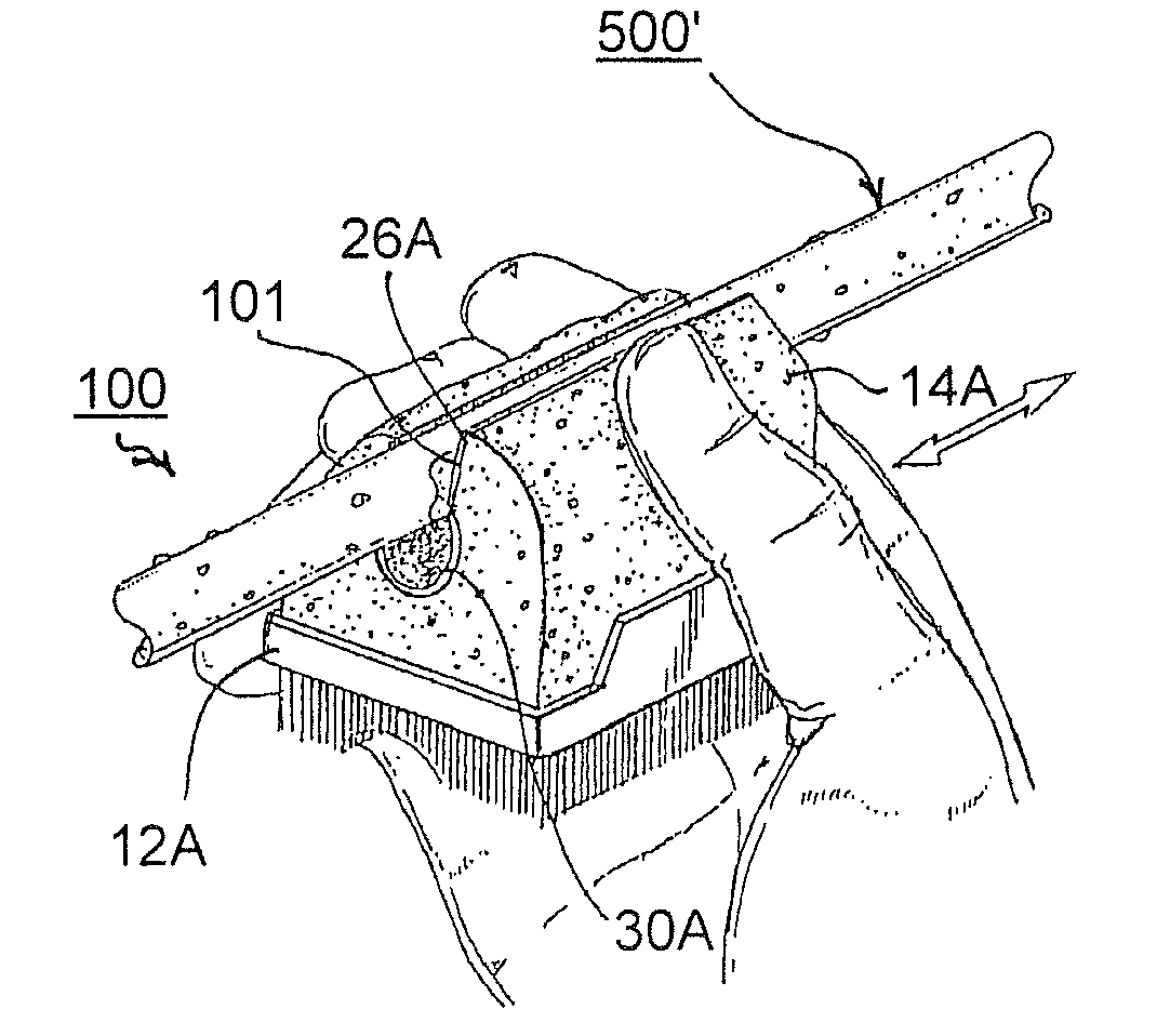
[0054]As will be noted specifically in FIGS. 6 and 7, while it is preferred to position the annular surface of medical instrument 500 within inner channel 30A, the present embodiment 100, provides an extension of flexible material 101 along the angled regions and parallel wall regions 26A, 28A, as noted in FIGS. 6 and 7. Consequently, as noted in FIG. 7, where opposing forces F′, F′ is directly applied sponge member 14A molds itself to the annular surface for effective cleaning. It is also important to recognize that flexible layer 101 may also be effective at removing organic debris when used without abrasive material (grit) by the use of mechanical abrasion with the woven or non-woven synthetic material.

embodiment 200

[0055]Referring now to FIG. 8, an alternative embodiment of the present scrub brush-sponge member 200 is provided including a flexible layer 101 within a sponge member 214 bonded to a brush base 212. In the present embodiment 200, brush base 212 is provided with additional extension gripping wings 201 that extend from side walls 238 and may optionally include gripping bumps 202 or any other kind of gripping aid that is flexible (openings, studs, projections, ridges, etc.).

[0056]The present embodiment for scrub brush-sponge member 200 is provided as an additional force embodiment allowing a user to grip the entire sponge with annular surface within the central U or C-shaped channel and provide additional pressure with gripping wings 201. Gripping wings 201 are not provided with a complete closure of the sponge body 214 so as to allow sufficient flexible space before contacting in the middle during a use (See FIG. 7 for example). As a consequence, gripping wings 201 allow for addition...

embodiment 300

[0058]Referring now to FIG. 9, an alternative embodiment 300 is provided with a bottom sponge member 314 and a top sponge member 314A. A polymeric and flexible binding bridge member 315 having a premetral side wall 316 is provided for bonding top and bottom sponge members respectively. It will be recognized that bridge member 316 may be shaped similarly to the central support member of bottom brush 12 discussed above, but with bristles 52 being replaced by the foam brush shaped as shown.

[0059]In the embodiment shown in FIG. 9, bottom sponge member 314 includes the flexible layer 101 along the C-shaped region 317, and an opposing U-shaped region 318 is formed in top sponge member 314A without a flexible layer 101, although a flexible layer may be provided in U-shaped region 318 without departing from the scope of the present invention. Consequently, embodiment 300 is provided with two opposing regions for scrubbing the annular surface of medical instrument 500, either or both of whic...


PUM

PropertyMeasurementUnit
flexibilityaaaaaaaaaa
flexibleaaaaaaaaaa
external compression forceaaaaaaaaaa

Abstract

A scrub brush-sponge includes a base provided with a recessed peripheral lip, which has a plurality of attenuated regions configured to minimize the resistance of the base to external bending forces, and a sponge coupled to the base and made from polymeric material, which may have as low a PPI as 10. The sponge is configured so that it can effectively surround at least a substantial peripheral portion of instruments or portions to be treated with fluid, which is contained within the sponge, without applying substantial external forces to the base. A flexible layer made of woven or non-woven bonded polymeric fibers is on a scrubbing surface of the sponge and provides an enhanced scrubbing feature. An abrasive may be included on the flexible layer to further enhance the scrubbing feature.

Description

CROSS REFERENCE TO RELATED APPLICATION[0001]This application is a continuation-in-part from, and claims priority to U.S. Ser. No. 11 / 141,938 filed Jun. 1, 2005, now U.S. Pat. No. 7,260,863, the entire contents of which are herein incorporated by reference.BACKGROUND OF THE INVENTION[0002]1. Field of the Invention[0003]The present invention relates to scrub sponges, and particularly, relates to scrub brush-sponges associated with a variety of medical procedures and adaptable for treating medical instruments.[0004]2. Description of the Related Art[0005]Numerous brush structures are known in the art. Some of these structures are functionally effective as well as convenient in use or ergonomic. While a minor amount of brush modification continues, surprisingly, scrub brushes used by medical professionals have not been substantially modified for quite some time. Structurally, a typical scrub brush has a base coupled to a rectangular sponge, which is saturated with antiseptic, germicide a...

Claims


Application Information

Patent Timeline
Patent Type & Authority Patents(United States)
IPC IPC(8): A47L13/12A47L13/16
CPCA46B7/04A61B19/34B08B1/00A46B15/0055A46B2200/3033A61B90/70
Inventor KAUFMAN, JACK W.KAUFMAN, LEGAL REPRESENTATIVE, JANETBROWN, JAMES
Owner BIOMED PACKAGING SYST
Why Eureka
Try Eureka