Sliding door latch assembly

a technology for sliding doors and latches, applied in the direction of wing accessories, mechanical controls, carpet fasteners, etc., can solve the problems of difficult to reach the location, difficult to operate the mechanism in its hidden location, and heavy weight of sliding doors, so as to eliminate the resultant interference with latch operation

Inactive Publication Date: 2007-08-28
BUILDERS HARDWARE
View PDF95 Cites 23 Cited by
  • Summary
  • Abstract
  • Description
  • Claims
  • Application Information

AI Technical Summary

Benefits of technology

[0008]It is an object of the invention to enable the use in sliding doors of larger handles that can be gripped by more than the fingertips while avoiding the difficulties that such placement of the handle causes when the handle in order to be adequate in size and shape tends to block the hand movement needed to reach the latch and latch lever. It is a further object to eliminate the resultant interference with latch operation and door locking and unlocking that use of larger handles has precipitated.
[0009]It is another object of the invention to provide a sliding door and latch assembly that provides a large handle for door shifting but is readily latched as well. It is a further object to provide an improved latch assembly that is accessible despite the presence of the larger handle. It is a still further object to provide a sliding door latch assembly that vertically spaces the latch and the latch lever such that the lever is accessible beyond the handle while the latch is within the housing locus where the handle is located. It is a further and specific object to provide an elongated, vertically disposed 4-bar coupling of the spaced latch and lever that translates the rotation of the lever into rotation of the latch for shifting the latch into or out of latching relation with the latch keeper.
[0010]These and other objects of the invention to become apparent hereinafter are realized in a sliding door latch assembly comprising a vertically extended housing having a vertically disposed pull handle opposite a housing locus extending over a major portion of but not all of the vertical extent of the housing, a latch mounted within the housing locus and shiftable to and from the housing for locking the sliding door to a cooperating keeper mounted in a sliding doorjamb opposite the latch, a rotary actuator within the housing locus for shifting the latch, a hand-operated lever rotatably mounted to the housing beyond the housing locus, the lever being vertically spaced a predetermined distance from the rotary actuator, the lever being rigidly linked to the rotary actuator for rotatably actuating the latch by the rotatable lever without having the lever within the housing locus, whereby hand actuation of the lever and latch is free of interference from the pull handle.

Problems solved by technology

Sliding doors are heavy and may not slide easily after a time.
This handle placement, however, leads to difficulties in operating the mechanism in its hidden and difficult to reach location.

Method used


Image

  • Sliding door latch assembly
  • Sliding door latch assembly
  • Sliding door latch assembly

Examples


Embodiment Construction

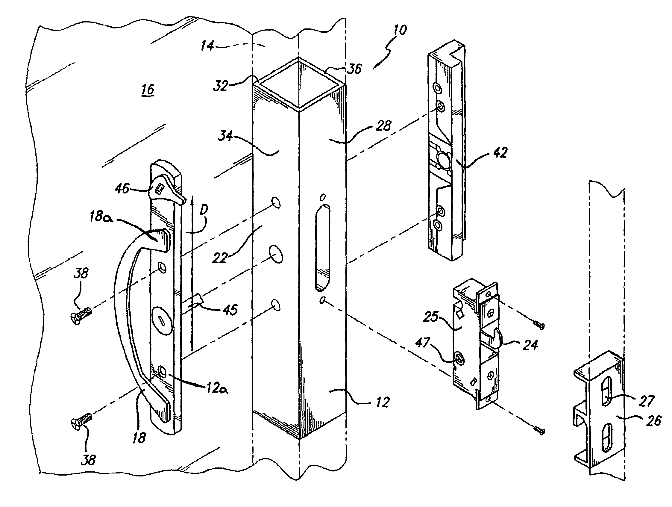
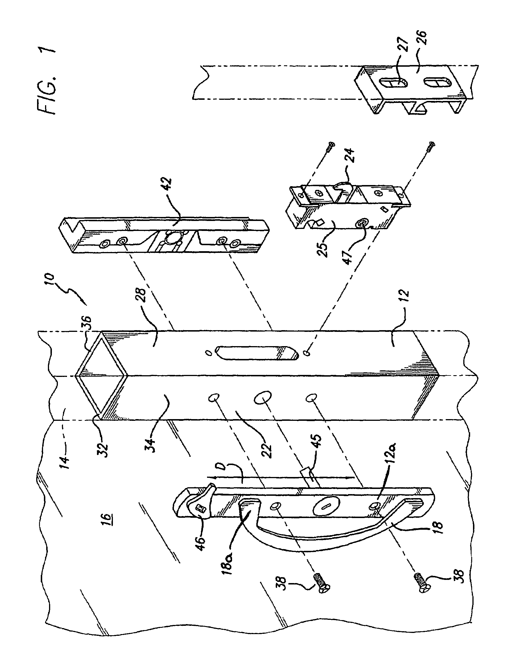
[0019]With reference now to the drawings in detail, in FIGS. 1 and 2 the invention sliding door latch assembly, generally indicated at 10, comprises a vertically extended housing 12 that is suitably a portion of the leading stile 14 of the sliding door 16. Secured to one side of the housing 12 is an escutcheon plate 12a and a vertically disposed pull handle 18 opposite a housing locus 22 extending over a major portion of but not all of the vertical extent of the housing. The handle 18 is connected to the escutcheon plate 12a at one or more connection points 18a. Extending from the front face of the escutcheon plate 12a is a lever 46, for actuation by a user. An actuator shaft 45 extends from the opposite face of the escutcheon plate 12a to mate with slot 47 on the latch housing 25. The latch 24 proper extends from latch housing 25 that is mounted within the housing locus 22, the latch being shiftable to and from the housing for locking the sliding door to a cooperating keeper 26 mou...


PUM


Abstract

A sliding door has a latch assembly and a vertically disposed pull handle that would normally interfere with convenient operation of the latch lever. A rotatable latch lever is located beyond the handle and a rotatable latch is located opposite the handle. A 4-bar coupling extends between the lever and the latch so that the latch is conveniently rotatable from beyond the pull handle for engaging a cooperating keeper.

Description

CROSS-REFERENCE TO RELATED APPLICATIONS[0001]This application is a continuation of U.S. application Ser. No. 09 / 613,294, filed Jul. 10, 2000 now U.S. Pat. No. 6,945,572, which claims the benefit of U.S. Provisional Application Ser. No. 60 / 214,493, filed Jun. 27, 2000.STATEMENT REGARDING FEDERALLY SPONSORED RESEARCH OR DEVELOPMENT[0002]Not ApplicableREFERENCE TO A MICROFICHE APPENDIX[0003]Not ApplicableBACKGROUND OF THE INVENTION[0004]1. Field of the Invention[0005]This invention relates to sliding door latch assemblies, and more particularly to the combination of a sliding door and latch assembly in which the latch, although behind or under the door pull handle, is conveniently operated by having the lever that operates the latch mounted beyond the area of the handle, and coupled to the latch by an elongated mechanism that translates the rotary action of the lever to rotary shifting of the latch from beyond the handle area.[0006]2. Description of the Related Art[0007]Sliding doors h...

Claims


Application Information

Patent Timeline
Patent Type & Authority Patents(United States)
IPC IPC(8): E05C19/10E05B55/00E05B53/00E05B65/08
CPCE05B65/0811E05B53/00Y10S292/46Y10T70/5173Y10T292/0828Y10T292/0929Y10T292/0946
Inventor HAUBER, PETER
Owner BUILDERS HARDWARE
Why Eureka
Try Eureka