Tibial knee prosthesis

a knee and prosthesis technology, applied in the field of knee prosthesis, can solve the problems of complex knee kinematics that are difficult to replicate, increase the complexity of knee kinematics, and combine shifting and pivoting of the femur

Active Publication Date: 2007-08-28
MICROPORT ORTHOPEDICS HLDG INC
View PDF71 Cites 100 Cited by
  • Summary
  • Abstract
  • Description
  • Claims
  • Application Information

AI Technical Summary

Benefits of technology

[0010]It is an object of the present invention is to provide a tibial knee prosthesis that allows for complex, combined motion of the femur with respect to the tibia which is believed to be more consistent with the natural motion of knees in deep flexion and allows for retention of the PCL in knee replacement surgeries.
[0011]It is a further object of the present invention is to provide a tibial knee prosthesis that allows for posterior and lateral motion during deep knee flexion, or in PCL-spared knees.
[0012]These and other objects of the invention are achieved by a tibial knee prosthesis having a medial concavity with a generally triangular shaped area bounded by an area of conformity. An anterior peak of the triangular shaped area facilitates effective low knee flexion activity wherein the medial femoral condyle primarily rotates with respect to the tibia. A wider posterior base of the generally triangular shape facilitates freer motion in moderate to deep flexion, including laterally directed motion from the PCL and posterior sliding with respect to the tibia.

Problems solved by technology

Such complex knee kinematics can be difficult to replicate using conventional knee prosthetics which are primarily intended to address more normal ranges of knee flexion.
Another issue associated with the implantation of knee prosthetics is that in some instances a surgeon may elect to retain the posterior cruciate ligament (PCL) of the knee when implanting tibial and femoral components of the knee prosthesis.
Regardless of the efficacy of sparing the PCL, its retention often increases the complexity of knee kinematics throughout the range of knee flexion.
In particular, PCL retention can result in combined shifting and pivoting of the femur with respect to the tibia due to its exertion of a laterally directed force on the femur.
Although these prosthetic devices provide one option to facilitate high knee flexion, they are relatively complex due to the required relative movement of the components with respect to their supporting bones.

Method used


Image

  • Tibial knee prosthesis
  • Tibial knee prosthesis
  • Tibial knee prosthesis

Examples


Embodiment Construction

[0034]The present invention now will be described more fully hereinafter with reference to the accompanying drawings, in which some, but not all embodiments of the invention are shown. Indeed, this invention may be embodied in many different forms and should not be construed as limited to the embodiments set forth herein; rather, these embodiments are provided so that this disclosure will satisfy applicable legal requirements. Like numbers refer to like elements throughout.

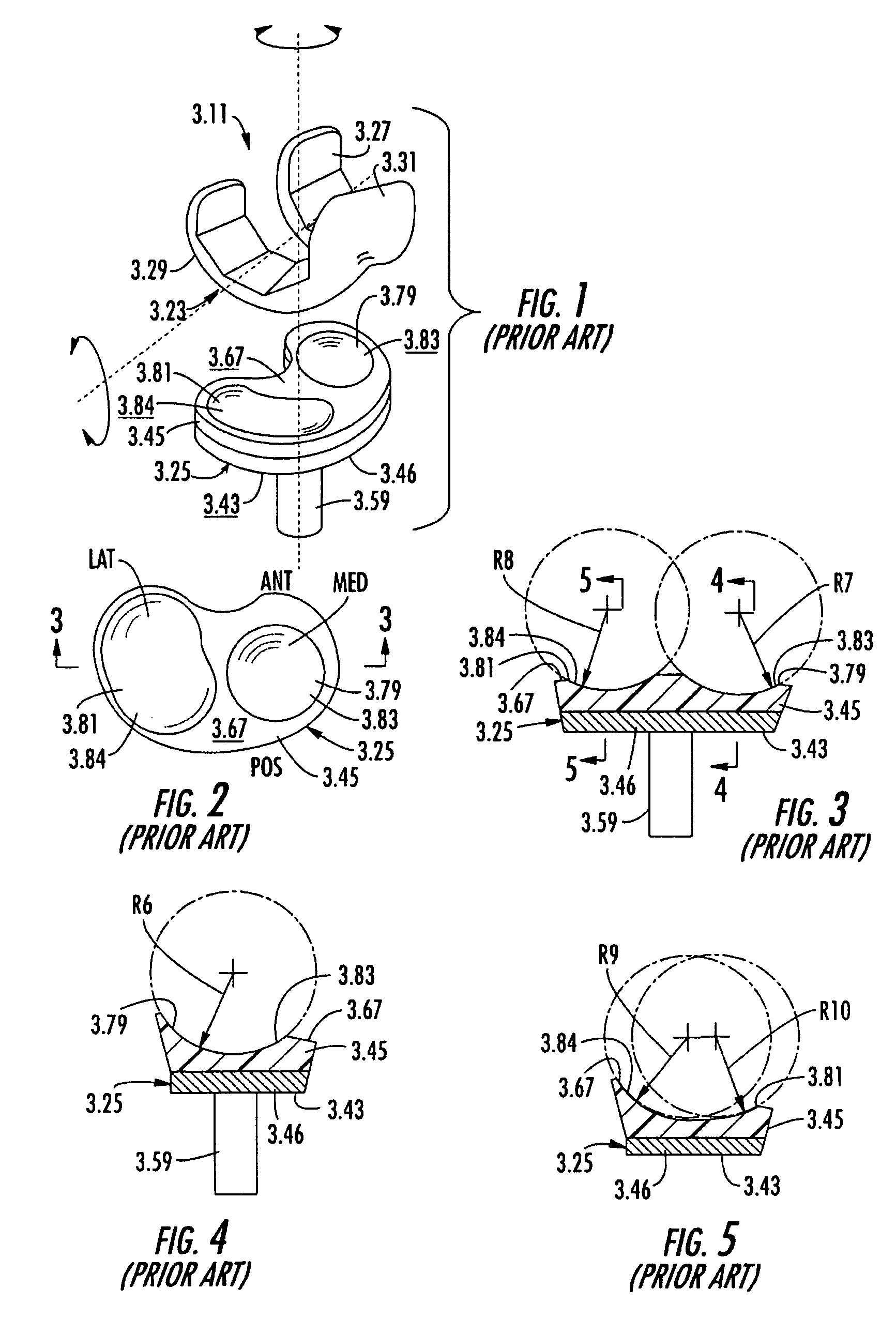
[0035]The invention is an improvement to the prior art medial pivot knee described in commonly assigned U.S. Pat. Nos. 5,964,808 and 6,013,103. The knee prosthetics taught by these patents will now be briefly described herein for context with respect to the exemplary preferred embodiment.

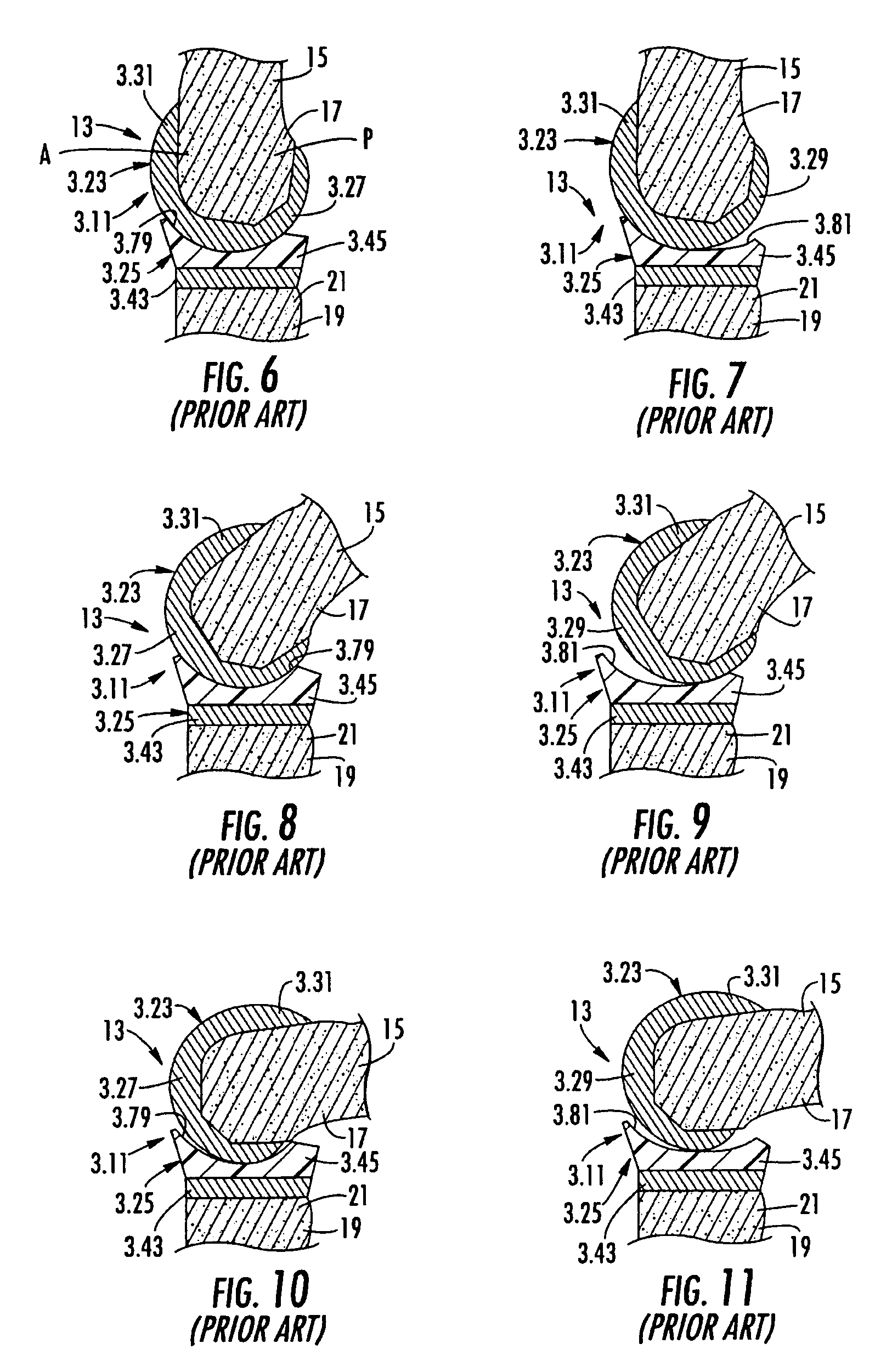
[0036]The knee prosthesis 3.11 is designed to replace at least a portion of a knee joint 13 between a distal end 17 of a femur 15 and a proximal end 21 of a tibia 19, as shown in FIGS. 6–11. The femoral component 3.23 includes, in...


PUM


Abstract

A knee prosthetic including a tibial component defining medial and lateral concavities shaped to receive medial and lateral femoral condyles of the femur. The concavities have first portions for contact with the condyles during normal knee flexion and second portions for contact with the condyles during deep, or high, knee flexion. The medial concavity can include a conforming boundary that encompasses at least the first and second portions, wherein an area inside the conforming boundary has a generally flat surface. The flat surface allows the medial femoral condyle to slide and rotate posteriorly during high knee flexion. The conforming boundary can have a generally triangular shape with an apex extending anteriorly and a relatively wider base extending posteriorly, wherein the apex includes the first portion and the base includes the second portion. The relatively wider base portion advantageously allows additional area for posteriorly directed articulating contact during high knee flexion.

Description

BACKGROUND OF THE INVENTION[0001]1. Field of the Invention[0002]The present invention is generally related to the field of knee prosthetics and specifically related to the field of tibial trays capable of providing high knee flexion with and without retention of the posterior cruciate ligament.[0003]2. Description of Related Art[0004]In U.S. Pat. No. 5,964,808 (the '808 patent) and U.S. Pat. No. 6,013,103 (the '103 patent) which are hereby incorporated herein by reference in their entirety, the assignee of the present patent application (Wright Medical Technology, Inc., of Arlington, Tenn.) introduced a knee prosthetic capable of better imitating the complex biomechanics and kinematics of the normal human knee. The knee prosthetic described in the '808 and '103 patents has been, and continues to be, successful, especially at facilitating movement within the normal ranges of knee flexion.[0005]Various scientific publications recognize that the kinematics of a normal, uninjured knee w...

Claims


Application Information

Patent Timeline
Patent Type & Authority Patents(United States)
IPC IPC(8): A61F2/38A61F2/30A61F2/00
CPCA61F2/389A61F2002/30133A61F2230/0015
Inventor TUTTLE, DAVID R.HARTDEGEN, VERNON R.WHITE, STEPHEN E.FENCL, ROBERT M.SCHMIDT, ROBERT H.
Owner MICROPORT ORTHOPEDICS HLDG INC
Why Eureka
Try Eureka