Saturation control of electric machine

a technology of saturation control and electric machines, applied in the direction of electric motor control, electrical apparatus, dynamo-electric machines, etc., can solve problems such as the inability to independently control the rotor speed

Active Publication Date: 2007-08-28
PRATT & WHITNEY CANADA CORP
View PDF143 Cites 48 Cited by
  • Summary
  • Abstract
  • Description
  • Claims
  • Application Information

AI Technical Summary

Benefits of technology

[0038]The present invention also advantageously permits load to be shared between a plurality of alternators / generators. The control winding controls the output current of the machine. Thus, referring to FIG. 5, if several alternators 10 are connected to simple rectifiers 60, the output of the rectifiers can be directly connected together such to feed a common load circuit. Each alternators contribution to the load current is set by control of the DC current (in this example) provided to each alternator from controlled source 50′. In this way, if a single alternator should fail or be shut down, a control system integrated in 50 can sense this and provide a seamless sharing of load by increasing the current contribution of one or more of the remaining alternators to preferably make up the deficit from the failed or shut down alternator.

Problems solved by technology

The output voltage and frequency of prior art PM alternators is determined by rotor speed, which present challenges where rotor speed cannot be independently controlled.

Method used


Image

  • Saturation control of electric machine
  • Saturation control of electric machine
  • Saturation control of electric machine

Examples


Embodiment Construction

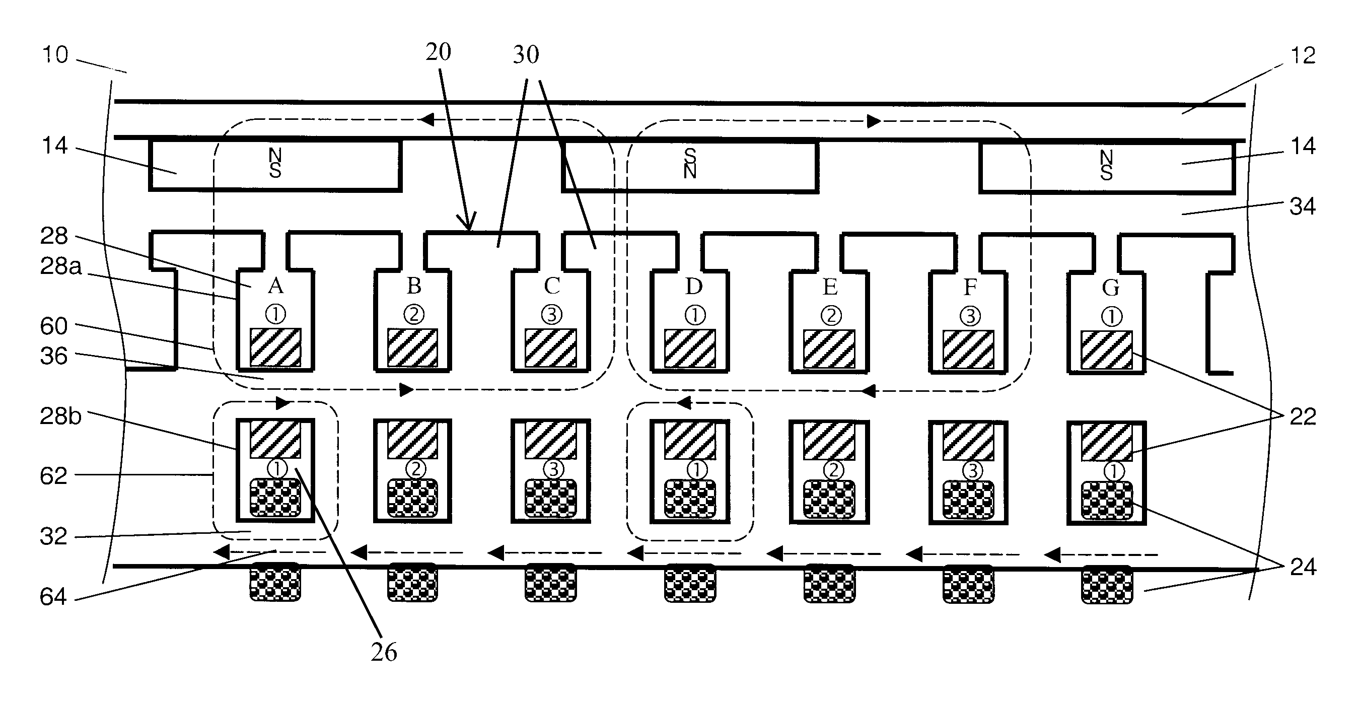
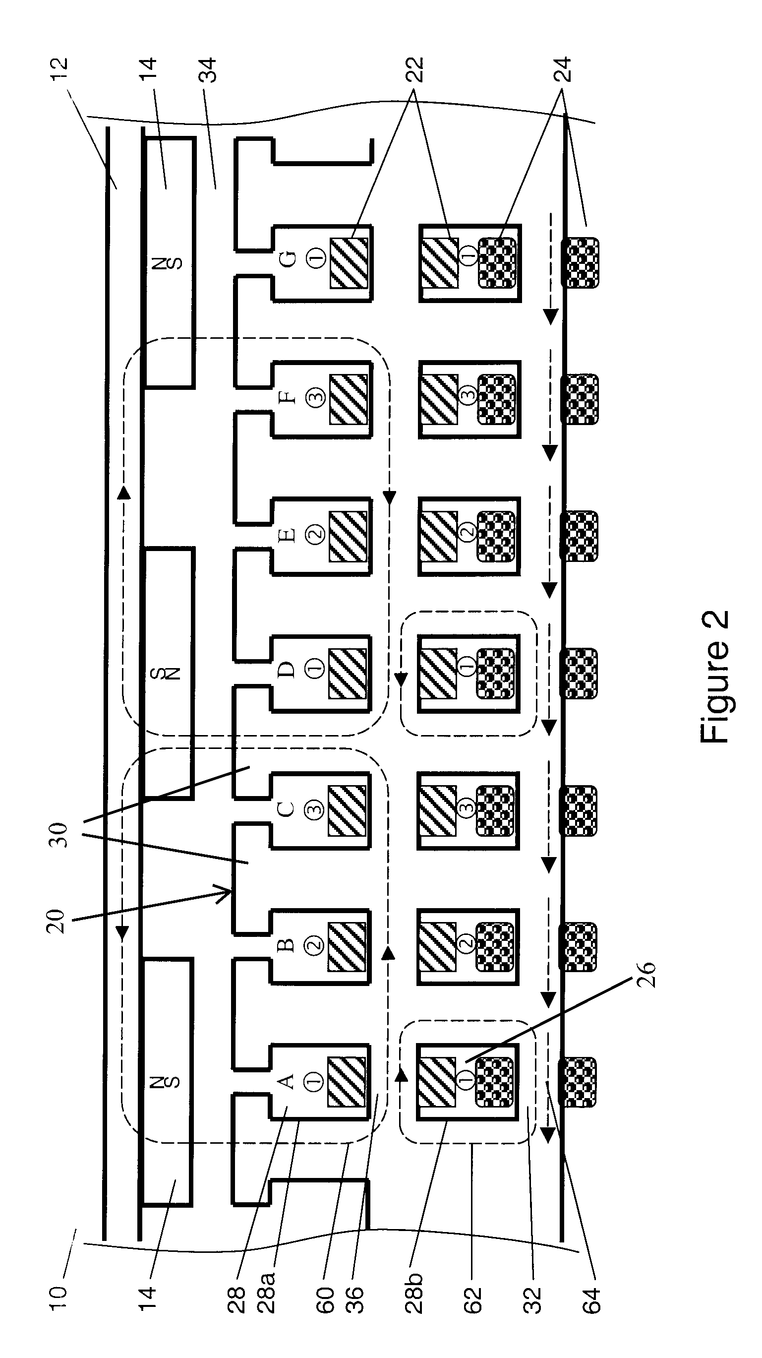
[0018]Referring to FIG. 2, a portion of a permanent magnet (PM) electric machine according to the present invention is depicted in at 10. For ease of illustration and description, FIG. 2 shows a linear arrangement of the electric machine 10, however it is to be understood that the machine is generally preferred to have a circular architecture, with an inside or outside rotor. It will also be understood by the skilled reader that FIG. 2 and the accompanying description are schematic in nature, and that many routine details of the design have been omitted for clarity. The machine 10 may be configured as an alternator to generate electrical power, or motor to convert electrical power into mechanical torque, or both. The description below is directed to an electric machine operable as both and alternator and motor.

[0019]Alternator / motor 10 has a rotor 12 with permanent magnets 14 which is mounted for rotation relative to a stator 20. Stator 20 has at least one power winding 22 and prefe...


PUM


Abstract

The invention includes an electric alternator / motor having a rotor, stator and at least one winding in the stator adapted to conduct a current, the machine also having and first and second magnetic circuits, one of which includes a saturable portion in which saturation may be controlled to permit control of the machine.

Description

CROSS REFERENCE TO EARLIER APPLICATION[0001]The applicant's co-pending U.S. patent application Ser. No. 10 / 444,952 is hereby incorporated by reference. The invention, however, is not necessarily limited to such architecture, as will become apparent to the skilled reader in light of the teachings herein.TECHNICAL FIELD[0002]The invention relates to electric machines such as alternators and motors, and in particular to the control of such machines.BACKGROUND OF THE ART[0003]Referring to FIG. 1, a typical permanent magnet (PM) alternator or motor has a rotor 102 supporting permanent magnets 104 and mounted on a rotatable shaft 108. A stator 110 has a plurality of windings 112 between a plurality of teeth 114 mounted to a back iron 116. (For ease of illustration, the adjacent elements of windings 112 in FIG. 1 are shown unconnected.) When operated in an alternator mode, an external torque source forces rotation of the shaft, and the interaction of the magnets and the windings causes a m...

Claims


Application Information

Patent Timeline
Patent Type & Authority Patents(United States)
IPC IPC(8): H02K21/00H02P9/32
CPCH02K21/046H02P31/00
Inventor DOOLEY, KEVIN ALLAN
Owner PRATT & WHITNEY CANADA CORP
Why Eureka
Try Eureka