Multi-angle colorimeter

a colorimeter and multi-angle technology, applied in the field of multi-angle colorimeters, can solve the problems of insufficient insufficient accuracy of approximation accuracy of mathematical functions, and inability to accurately correct the influence of orientation errors

Active Publication Date: 2007-08-28
KONICA MINOLTA SENSING INC
View PDF1 Cites 24 Cited by
  • Summary
  • Abstract
  • Description
  • Claims
  • Application Information

AI Technical Summary

Problems solved by technology

(1) Initial directional error: This error is caused because the angles from the normal of the sample surface to be measured (anormal angles, hereafter) of the illumination and the receiving are deviated from the nominal angles due to various manufacturing errors.
(2) Orientation error: This error is caused by the disagreement between the normal of the sample surface and the reference axis of the measuring device both of which are to be in coincidence ideally. This error readily occurs when the sample surface is not a plane.
These geometry errors significantly affect the measurement stability particularly in the vicinity of the specular reflection direction where the directional dependence of the reflection characteristics is very high.
However, the above-described method doesn't correct the influence of the orientation error accurately since the illumination from the direction of 45 degrees anormally in typical multi-angle colorimeters is used as the illumination for detecting the orientation error.
For this reason, the approximation accuracy of the mathematical function is generally insufficient, and accordingly the accuracy of the orientation error estimated based on the approximation function is also insufficient.

Method used


Image

  • Multi-angle colorimeter
  • Multi-angle colorimeter
  • Multi-angle colorimeter

Examples


first embodiment

Correction of the Orientation Error

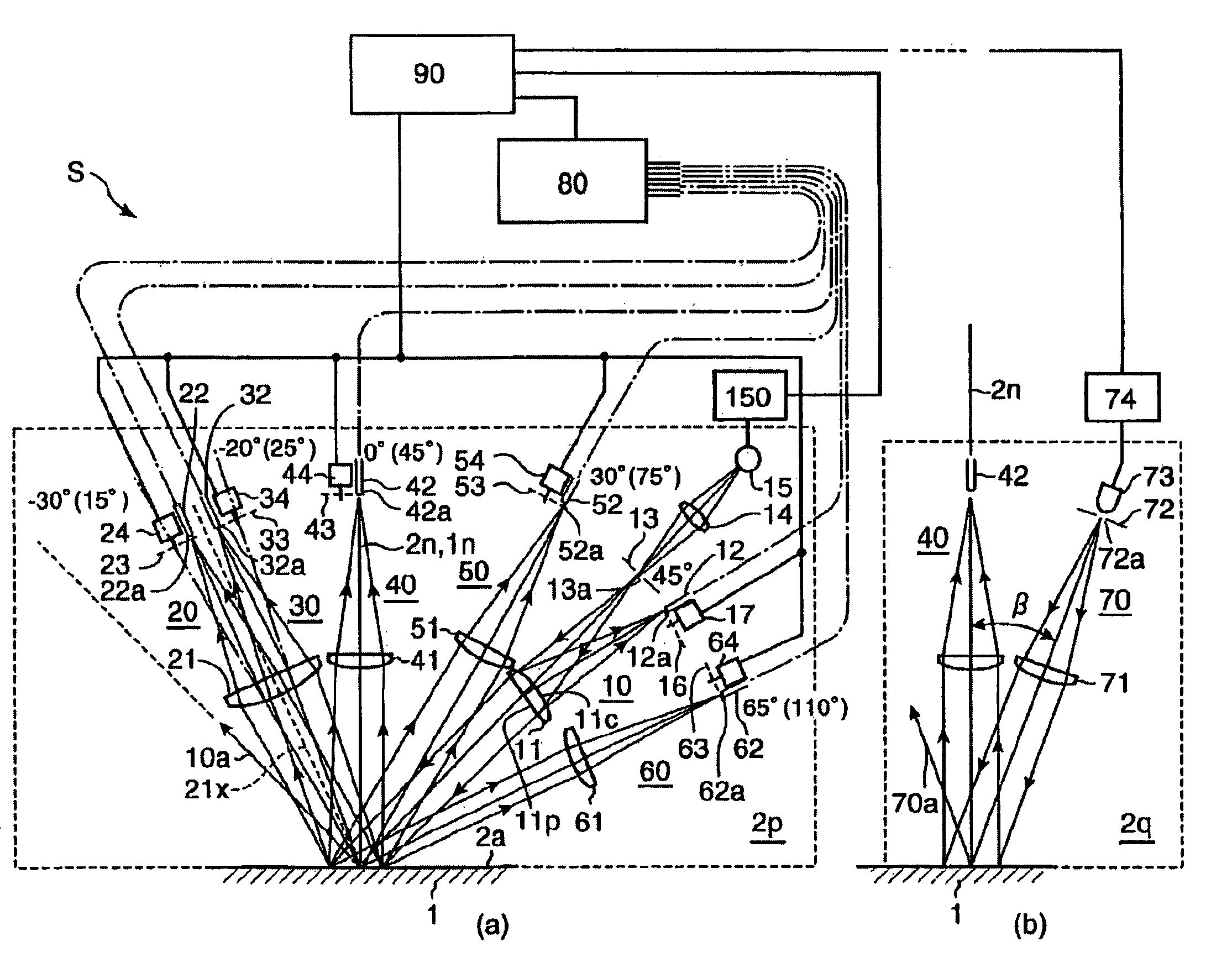
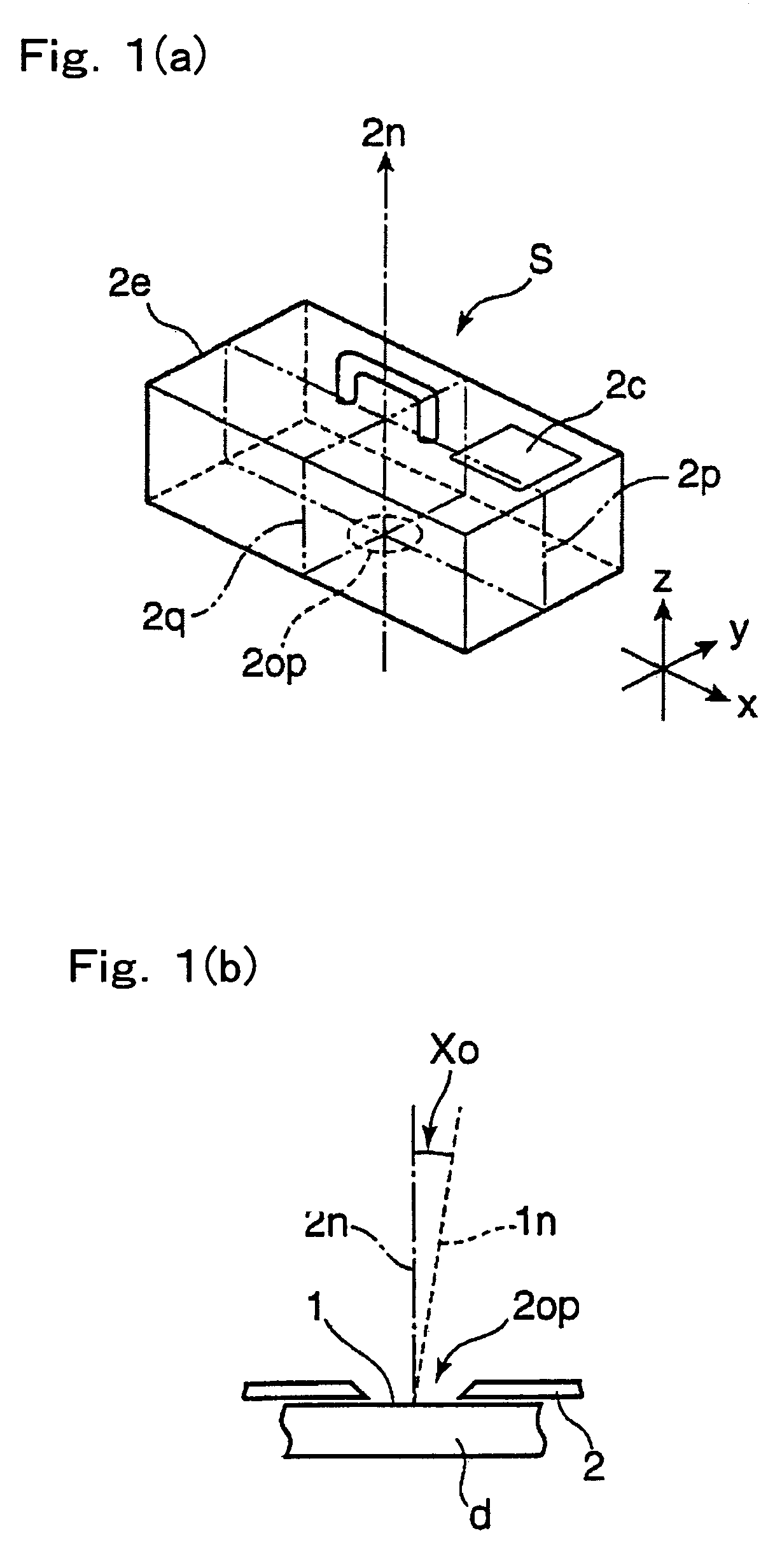
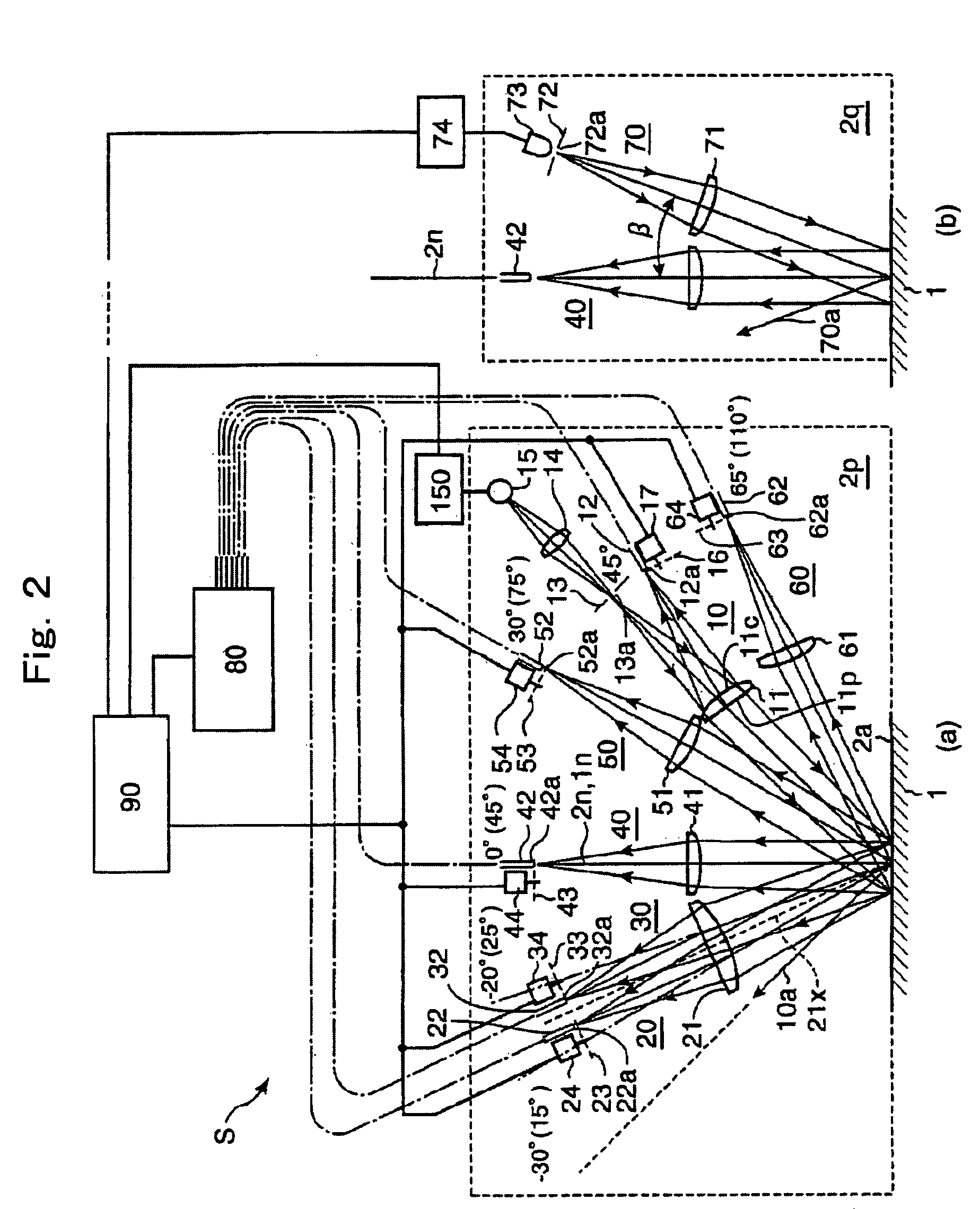
[0045]FIG. 1(a) is a perspective view schematically showing the appearance of a multi-angle colorimeter S. This multi-angle colorimeter S has a box-shaped body case 2e in which components such as an illumination system, a light receiving system or the like described later are housed. The bottom surface of the body case 2e is a measurement aperture surface 2. On the measurement aperture surface 2, a measurement aperture 2op of an appropriate shape (for example, an oval) is formed. In an appropriate position on the surface of the body case 2e, a display 2c for showing the measurement result and the like are disposed. The multi-angle colorimeter S is portable and handheld.

[0046]Then, the calorimetric measurement of the sample surface 1 (for controlling metallic colors for example) is performed with the measurement aperture 2op of the multi-angle colorimeter S being opposed to a sample surface 1 of a measurement sample d (the exterior surface of a car ...

second embodiment

Correction of the Initial Angular Error

[0144]As described above, when measuring the coating 110 containing the special effect flake pigments 111 by the multi-angle colorimeter S, since the reflection characteristic of the coating 110 is highly directional dependent, not only the orientation error described above but also an error in the aspecular angle of each light receiving direction the multi-angle colorimeter S initially has, bring about an error in the reflection characteristics measurement. For this reason, it is desirable to manufacture a multi-angle colorimeter S with the initial angular error as close to zero as possible. However, in actuality, the light receiving directions unavoidably deviates from the nominal directions due to various manufacturing errors, and the initial angle error is inevitable. In particular, the initial angle error brings about a significant reflection characteristic error in the receiving direction close to the specular reflection direction where t...


PUM

PropertyMeasurementUnit
aspecular angleaaaaaaaaaa
angleaaaaaaaaaa

Abstract

In a multi-angle colorimeter having an illumination system that illuminates a sample surface and a plurality of light receiving systems that receive reflected light therefrom, an illumination system for orientation error detection is provided that illuminates the sample surface from substantially close direction to the normal of the sample surface. Actual measured reflectance factor is corrected based on the specific approximation function obtained from the measured reflectance factor and detected orientation error.

Description

[0001]This application is based on the application No. 2004-188147 filed in Japan, the contents of which are hereby incorporated by reference.BACKGROUND OF THE INVENTION[0002]1. Field of the Invention[0003]The present invention relates to a multi-angle colorimeter for measuring a gonio-apparent coating such as a metallic coating or a pearlescent coating, and more particularly, to a multi-angle colorimeter having a function for correcting the geometry errors.[0004]2. Description of the Related Art[0005]In metallic coatings and pearlescent coatings used primarily for an automotive coating, tiny flakes of aluminum or mica called special effect pigment are contained within the coating, and this produces a so-called metallic effect or pearlescent effect. This is due to the fact that the contribution of the special effect pigment to the reflection characteristic differs according to the illumination and the viewing direction. For the evaluation (calorimetric measurement) of such coatings,...

Claims


Application Information

Patent Timeline
Patent Type & Authority Patents(United States)
IPC IPC(8): G01J3/46G01J3/02G01J3/50G01N21/57
CPCG01J3/02G01J3/0218G01J3/0267G01J3/0278G01J3/504G01N21/57G01N2021/575
Inventor IMURA, KENJI
Owner KONICA MINOLTA SENSING INC
Why Eureka
Try Eureka