Handle assembly for refrigerator

a technology for refrigerators and handles, applied in the direction of wing knobs, domestic cooling devices, lighting and heating devices, etc., can solve the problems of deterioration of the external appearance of the door liner b>2/b>i>b /i>, limitation of the thickness design of the insulating layer formed between the front plate, and further complicated door liners. achieve the effect of reducing production costs and being easy to assembl

Inactive Publication Date: 2007-09-04
LG ELECTRONICS INC
View PDF21 Cites 62 Cited by
  • Summary
  • Abstract
  • Description
  • Claims
  • Application Information

AI Technical Summary

Benefits of technology

[0016]A further object of the present invention is to provide a handle assembly which makes its assembling process easy.
[0029]According to the present invention so constructed, the man-hour needed for the assembling works can be reduced since the number of parts consisting of the handle assembly is minimized, causing the production costs to be reduced. Further, there are advantages in that the external appearance of the handle assembly and the door can be made elegant and in that it is easy to assemble the handle assembly to the door.

Problems solved by technology

However, the handle assembly for the refrigerator according to the prior art as described above has the following problems.
That is, in the prior art, since the separate fastening grooves 2c should be formed in the door liner 2b, the door liner 2b are further complicated.
In addition, due to the existence of the fastening grooves 2c, there is a limitation on a thickness design of an insulating layer formed between the front plate 2a and the door liner 2b.
Therefore, there is a problem in that the external appearance of the door liner 2b is relatively deteriorated.
That is, it causes the problem that a process of fastening the screws Sb is relatively cumbersome because a worker are positioned opposite to the object to be fastened with respect to the door 2.

Method used


Image

  • Handle assembly for refrigerator
  • Handle assembly for refrigerator
  • Handle assembly for refrigerator

Examples


first embodiment

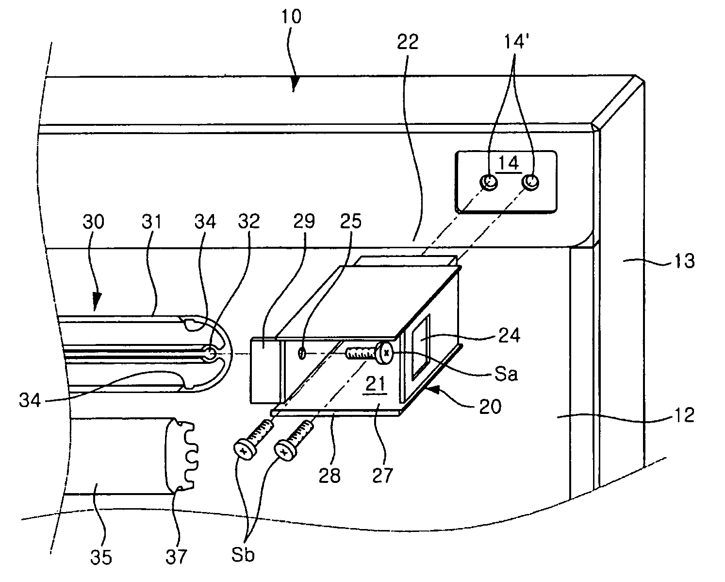
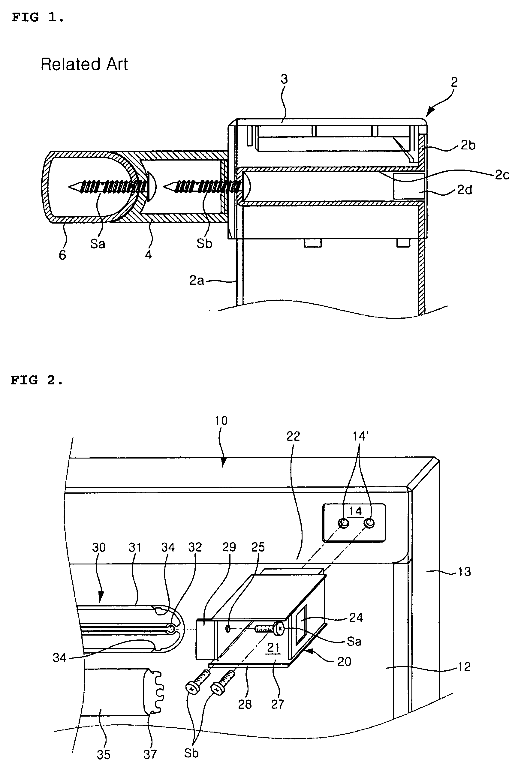
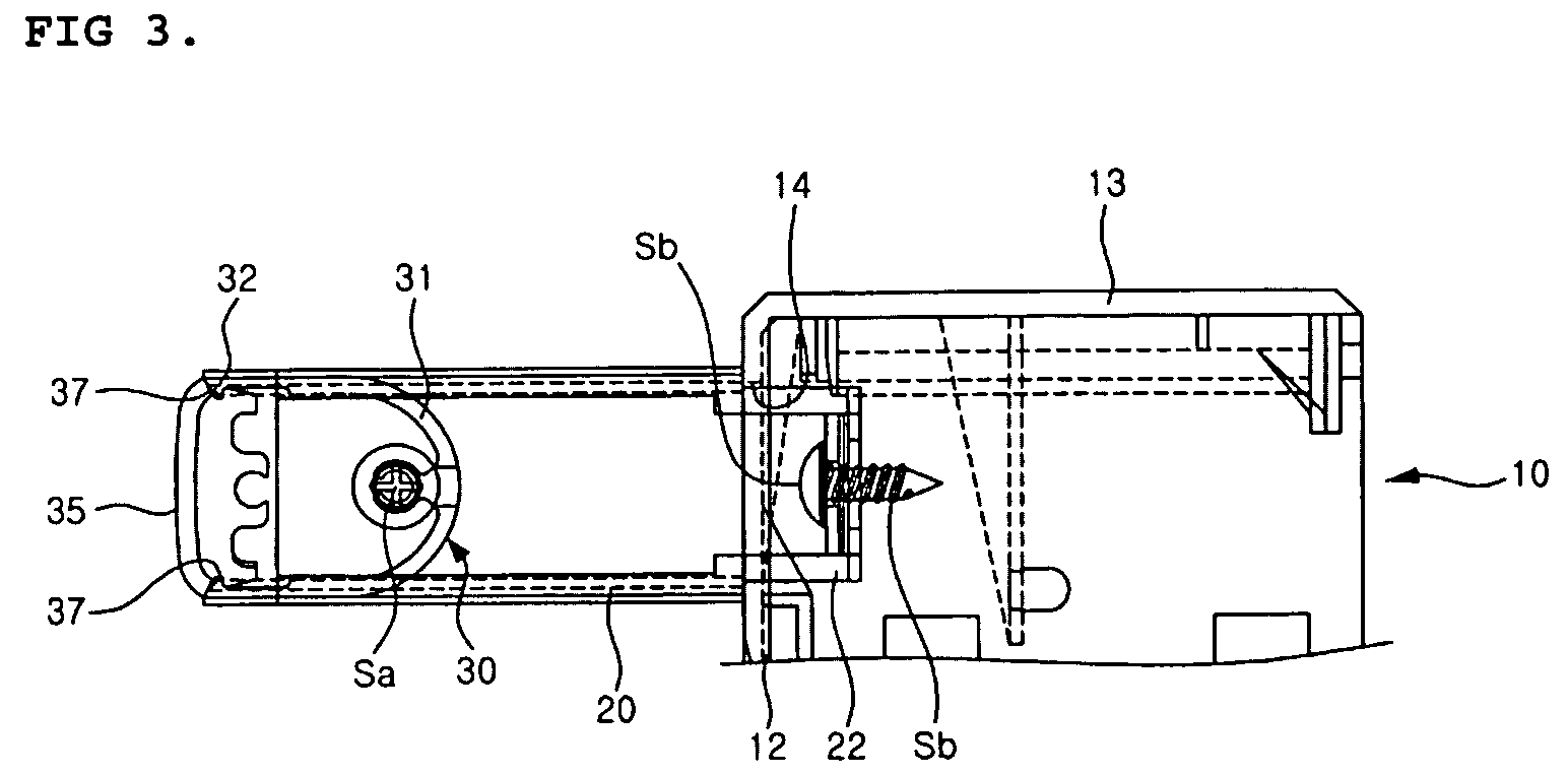
[0057]Then, in order to securely mount the fixing holder 120 to the door 110, as in the first embodiment, a front surface of the door 110 in which the fastening holes 112 are formed may be relatively concaved, and a rear end of the fixing holder body 121 corresponding thereto may be formed to protrude in the shape corresponding to the concave portion formed in the front surface of the door 110. It is preferred that the concave portion of the door 110 and the protruding portion of the fixing holder body 121 be formed in shapes not to rotate with respect to each other.

[0058]Catching pieces 123 are provided at both sides of a front end of the fixing holder body 121 to face each other. Each of the catching pieces 123, which is shaped into a quadrangular plate, is extended to the front of the fixing holder body 121 by a predetermined length. Catching projections 124 are formed on distal ends of the catching pieces 123 to face each other. The respective catching projections 124 are formed...

second embodiment

[0073]Next, an assembling process of the present invention will be described with reference to FIG. 6.

[0074]First, at the front of the door, the fixing holder 120 and the handle holder 125 are mounted on the front surface of the door 110. That is, screws Sc penetrate the fastening holes 121′ of the fixing holder body 121 and the fastening holes 126′ of the handle holder body 126 and then are fastened into the fastening holes 112 of the front surface of the door 110, respectively. Such a state is shown in FIG. 6a.

[0075]Next, as shown in FIG. 6b, the handle 130 is engaged to the handle holder 125. That is, the connection boss 128 of the handle holder body 126 is press fitted into the vent hole 132 opened to the lower end of the handle 130. At this time, the portion of the outer surface of the handle 130 is in contact with the seating surface 121f of the handle holder body 126.

[0076]After engaging the lower end of the handle 130 to the handle holder 125, as shown in FIG. 6c, the upper...


PUM


Abstract

The present invention relates to a handle assembly for a refrigerator. According to the present invention, there is provided a handle assembly for a refrigerator. The handle assembly comprises a pair of handle holders each of which is formed with a cavity therein and mounted onto a front surface of a door by means of a screw that is fastened to the front surface of the door through the cavity; a handle body which is positioned between the handle holders and which is fastened to the handle holders by means of screws that penetrate the handle holders and are fastened thereto; and a handle cover elastically mounted to front ends of the handle holders and the handle body. According to the present invention, since the handle assembly can be mounted to the front surface of the door at the front of the door, the man-hour needed for the assembling works and the production costs can be reduced. Further, the external appearance of the handle assembly and the door can be made more elegant and the handle assembly can also be easily assembled to the door.

Description

[0001]This Nonprovisional application claims priority under 35 U.S.C. § 119(a) on patent application No(s). 10-2003-0067583 and 10-2003-0073551 filed in Republic of Korea on Sep. 29, 2003 and Oct. 21, 2003, respectively, the entire contents of which are hereby incorporated by reference.BACKGROUND OF THE INVENTION[0002]1. Field of Invention[0003]The present invention relates to a handle assembly for a refrigerator, and more particularly, to a handle assembly for a refrigerator which is gripped and operated by a user in order to open and close a door of the refrigerator.[0004]2. Description of the Prior Art[0005]A front surface of a door of a refrigerator is mounted with a handle assembly which is gripped by a user when the door is opened and closed. FIG. 1 is a transverse sectional view of a major portion of a handle assembly for a refrigerator according to a prior art. According to the figure, a front plate 2a and a door liner 2b define front and rear external appearances of a door ...

Claims


Application Information

Patent Timeline
Patent Type & Authority Patents(United States)
IPC IPC(8): E05B1/00F25D23/02
CPCE05B1/0015F25D23/028A47B95/02Y10T16/458Y10S16/40Y10T16/498
Inventor KIM, MYOUNG-KOOKJUNG, SANG-HO
Owner LG ELECTRONICS INC
Why Eureka
Try Eureka