Fin stabilizer for vessel and control method and control program therefor

a technology for stabilizers and vessels, applied in special-purpose vessels, vessel movement reduction by foils, transportation and packaging, etc., can solve the problems of inability to achieve the lifting force required for the angle of the above-ground attack and the fin angle may not match in some cases, and the inability to control the fin angle at an appropriate angle. achieve the effect of suppressing the rocking motion of the vessel body and high level of accuracy

Active Publication Date: 2007-09-04
MITSUBISHI HEAVY IND LTD
View PDF10 Cites 8 Cited by
  • Summary
  • Abstract
  • Description
  • Claims
  • Application Information

AI Technical Summary

Benefits of technology

[0008]An object of the present invention is to provide a fin stabilizer for a vessel that can suppress the rocking motion of a vessel body with a high level of accuracy by obtaining a required lifting force, and a control method and control program therefor.

Problems solved by technology

However, under the influence of wave disturbance and motion of the vessel body, the above angle of attack and fin angle may not match in some cases.
In this case, in the above mentioned conventional fin stabilizer, there has been a problem in that the fin angle cannot be controlled at an appropriate angle and a required lifting force for suppressing rocking motion of the vessel body cannot be achieved.

Method used


Image

  • Fin stabilizer for vessel and control method and control program therefor
  • Fin stabilizer for vessel and control method and control program therefor
  • Fin stabilizer for vessel and control method and control program therefor

Examples


first embodiment

[0030]Hereunder, a fin stabilizer for a vessel according to a first embodiment of the present invention is described.

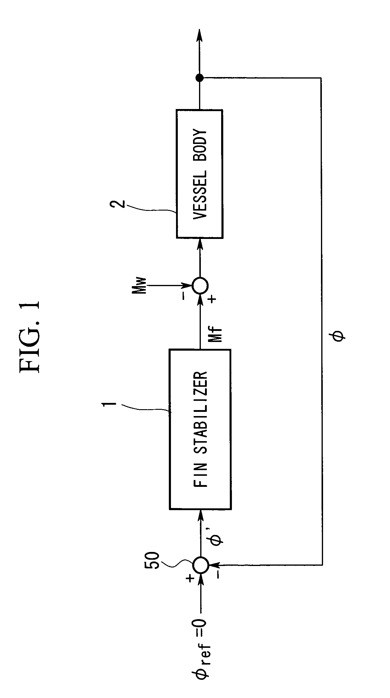
[0031]FIG. 1 is a control block diagram for explaining an effect of a fin stabilizer for a vessel (hereunder referred to as “fin stabilizer”) according to the present embodiment, on a vessel body.

[0032]As shown in this diagram, a sensor (not shown in the diagram) provided on a vessel body 2 detects an actual inclination angle φ of the vessel body 2 and enters it into a target inclination angle generation section 50. In the target inclination angle generation section 50, an inclination angle command value φ′ for matching the actual inclination angle φ of the vessel body 2 to a target inclination angle φref (=0) is calculated, and this inclination angle command value φ′ is outputted to a fin stabilizer 1. The target inclination angle generation section 50, for example, outputs a difference between the target inclination angle φref and the actual inclination angle φ of t...

second embodiment

[0051]Next, a second embodiment of the present invention is described, with reference to FIG. 6.

[0052]A fin stabilizer of the present embodiment differs from that of the first embodiment in that in the feed back system, a predetermined condition is added, and the fin angle to be fed back is switched between either the estimated angle of attack θ2′ or the actual fin angle θ3′ according to this condition.

[0053]For the fin stabilizer according to the present embodiment, in the case where, for example, a difference between the estimated angle θ2′ and the actual fin angle θ3′ is less than or equal to a predetermined value (for example, 2°) and a rocking motion cycle of the vessel body 2 (refer to FIG. 1) is greater than or equal to a preset predetermined threshold value (for example, 20 seconds), the estimated angle of attack θ2′ is fed back.

[0054]Conversely, in the case where the above condition is not satisfied, that is, in the case where the difference between the estimated angle of a...


PUM


Abstract

An object is to suppress the rocking motion of a vessel body with a high level of accuracy by obtaining a required lifting force. A torque calculation section 27 calculates a torque of a fin 11 based on the pressure of a hydraulic cylinder 12. This torque is inputted to an angle of attack computing unit 24 via a torque adjusting unit 28, and based on this torque, a fin angle with respect to a flow of sea water, that is, an angle of attack of the fin is estimated. Then a command generation section 23 generates a fin angle command value θ3 for matching the estimated angle of attack θ2′ with a target fin angle θ1. Based on this fin angle command value θ3, a flow rate adjusting mechanism 14 controls a flow rate Q of hydraulic fluid applied to the hydraulic cylinder 12, to thereby adjust the angle of the fin 11. Thus, the fin angle is controlled based on the angle of attack, which directly relates to lifting force.

Description

BACKGROUND OF THE INVENTION[0001]1. Field of the Invention[0002]The present invention relates to a fin stabilizer for a vessel for suppressing a rocking motion of the vessel body.[0003]This application is based on Japanese Patent Application No. 2005-118421, the content of which is incorporated herein by reference.[0004]2. Description of Related Art[0005]Conventionally, as an apparatus for suppressing the rolling motion and pitching motion of a vessel body there is known, for example, a fin stabilizer (for example, refer to Japanese Unexamined Patent Application, First Publication No. H08-324485). This fin stabilizer has a fin provided on and projecting from an outer panel of the vessel and by controlling an angle of this fin a lifting force is generated to suppress the rolling motion of the vessel body.[0006]In such a fin stabilizer, a fin angle with respect to sea water flow (hereunder referred to as “angle of attack”) and a fin angle with respect to the vessel body (hereunder ref...

Claims


Application Information

Patent Timeline
Patent Type & Authority Patents(United States)
IPC IPC(8): B63B39/00
CPCB63B39/06
Inventor DOBASHI, SHUJIMATSUNAGA, KATSUHIDEOGAHARA, TATSUNORI
Owner MITSUBISHI HEAVY IND LTD
Why Eureka
Try Eureka