Improper working position detection for tire mounting apparatus and method

a technology of working position detection and tire mounting, which is applied in the direction of wheel, tire repairing, vehicle components, etc., can solve the problem that the tire bead deflector cannot maintain at least a prescribed minimum spacing distance, and achieve the effect of ensuring the trouble-free performance of the tire mounting process and avoiding damage to the tire, rim or equipmen

Inactive Publication Date: 2007-09-04
SCHENCK ROTEC GMBH
View PDF10 Cites 19 Cited by
  • Summary
  • Abstract
  • Description
  • Claims
  • Application Information

AI Technical Summary

Benefits of technology

[0006]In view of the above, it is an object of the invention to improve a tire mounting apparatus and method of the above mentioned general type in such a manner so as to ensure the trouble free performance of the tire mounting process, even for a succession of wheel rims of different types or sizes. A further object of the invention is to avoid damage to the tire, rim or equipment due to an improper working position and especially contact between the bead deflector and the wheel rim flange. The invention further aims to avoid or overcome the disadvantages of the prior art, and to achieve additional advantages, as apparent from the present specification. The attainment of these objects is, however, not a required limitation of the claimed invention.
[0010]Advantageously, the invention provides that an improper working position between the tire mounting head and the wheel rim possibly arising before or even during the tire mounting process is detected and produces a signal that suitably influences the tire mounting process. For example, the tire mounting process is not started, or the already-started tire mounting process is interrupted and the apparatus is stopped, or the tire mounting head is repositioned relative to the wheel rim. The improper working position of the mounting head, and especially the bead deflector thereof, relative to the wheel rim can arise from any of the above mentioned errors, such as errors in the wheel rim type recognition or in the transmission of the type identifying data, or errors in the adjustment of the bead deflector or the press-in roller, or errors in the support and clamping of the wheel rim. The invention provides simple means to ensure that such in improper working position does not lead to damage of the wheel rim or the tire, for example because the further operation of the tire mounting apparatus is immediately stopped if any such improper working position is detected. Then, an operator of the apparatus can determine the cause of the problem, and carry out any suitable readjustment or repositioning (for example repositioning and reclamping the wheel rim, or readjusting the position of the bead deflector or the press-in roller especially regarding the axial positions thereof). Thereafter the tire mounting process can be started or continued, without having caused any damage to the tire or the rim. Thereby the reject rate can be significantly reduced.
[0011]It is also advantageous that the invention does not require complex or costly additional devices, because the position or spacing detection arrangement is preferably incorporated into the existing bead deflector in a simple manner. An especially advantageous further embodiment provides a wireless signal transmission from the position detection arrangement of the bead deflector to the drive arrangement or the controller thereof. Thereby a hard-wired cable connection can be omitted, although an alternative embodiment uses a hard-wired transmission of an electrical signal through an electrical cable connection or of an optical signal through an optical fiber connection. Such cable connections can be problematic and subject to interference or breakdown in the actual production process, especially if the cables must undergo rapid movements in operation, in this case the axial and circular or rotational movements of the tire mounting head. The preferred wireless transmission according to the invention preferably is carried out as a radio transmission (e.g. radio frequency RF transmission), but alternatively may be carried out as an optical transmission (e.g. an infrared IR transmission).

Problems solved by technology

In the improper working position, the tire bead deflector fails to maintain at least a prescribed minimum spacing distance between the tire bead deflector and the wheel rim.

Method used


Image

  • Improper working position detection for tire mounting apparatus and method
  • Improper working position detection for tire mounting apparatus and method
  • Improper working position detection for tire mounting apparatus and method

Examples


Embodiment Construction

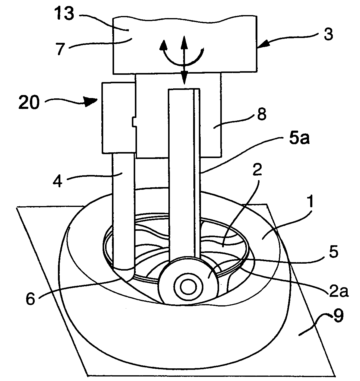
[0020]FIG. 1 schematically illustrates an apparatus for mounting a tire 1 onto a wheel rim 2 of a vehicle wheel. The tire mounting apparatus is arranged and supported in a machine frame or tire mounting station, of which the further components are not shown. The wheel rim 2 is supported on a wheel support platform 9, which is schematically indicated, and which includes any conventionally known wheel holding or clamping device. The wheel rim 2 is thus fixedly secured and held in the horizontal position on the wheel support platform 9 by the wheel rim clamping device (not shown in detail) thereof.

[0021]Above the wheel rim 2, the tire mounting or draw-down head 3 of the tire mounting apparatus is movably arranged on the machine frame so that the rotation axis of the tire mounting head 3 coincides with the vertical wheel rim axis of the wheel rim 2. More particularly, the mounting head 3 is connected to and supported by a drive arrangement 13 so as to be rotatable by at least one rotati...


PUM


Abstract

An apparatus for mounting a tire on a wheel rim includes a mounting head with a tire bead deflector and a tire press-in roller, and a drive that moves the mounting head toward, and rotates the bead deflector and the press-in roller around, the wheel rim. To avoid a damage-causing contact between the bead deflector and the wheel rim, an arrangement for monitoring a minimum spacing distance between the wheel rim and the mounting head is arranged preferably on the bead deflector. If an improper working position closer than the minimum spacing distance is detected, the arrangement produces a signal that influences, e.g. stops, the motion of the mounting head. The arrangement preferably includes a contact member of a comparatively soft low-friction material at a working end of the bead deflector. If the contact member contacts the wheel rim, this actuates a piezoelectric element to generate the required electrical signal.

Description

PRIORITY CLAIM[0001]This application is based on and claims the priority under 35 U.S.C. §119 of German Patent Application 10 2004 040 866.1, filed on Aug. 23, 2004, the entire disclosure of which is incorporated herein by reference.FIELD OF THE INVENTION[0002]The invention relates to a method and an apparatus for mounting a tire onto a rim of a vehicle wheel, using a tire mounting head with a bead deflector and a press-in roller as well as a drive for rotating the mounting head about the wheel rim axis and for axially moving the mounting head.BACKGROUND INFORMATION[0003]A tire mounting apparatus and method of the above mentioned general type are known from the company catalog “Balancing and Diagnostic Systems”, 2002 Catalog RA 1020e of the company Schenck RoTec GmbH, of Landwehrstrasse 55, D-64293 Darmstadt, Germany. At pages 116 and 117, the English version of the mentioned catalog discloses a tire mounting or assembly machine for vehicle wheels, whereby the tire is at first laid ...

Claims


Application Information

Patent Timeline
Patent Type & Authority Patents(United States)
IPC IPC(8): B60C25/135B60C25/12B60C25/122B60C25/132
CPCB60C25/132
Inventor PEINELT, ANDREASLEHR, WERNER
Owner SCHENCK ROTEC GMBH
Why Eureka
Try Eureka