Controlled deployment delivery system

a delivery system and stent technology, applied in the field of medical devices and procedures, can solve the problems of re-positioning the stent-graft, reducing the retraction rate, so as to achieve the effect of avoiding the retraction ra

Active Publication Date: 2007-09-04
MEDTRONIC VASCULAR INC
View PDF12 Cites 364 Cited by
  • Summary
  • Abstract
  • Description
  • Claims
  • Application Information

AI Technical Summary

Problems solved by technology

Such a configuration leaves little room for error in placement since re-positioning the stent-graft after initial deployment, except for a minimal pull down retraction, is usually difficult if possible at all.
Unfortunately, this method introduced a separate non-integrated sheath into the system into the femoral artery and further failed to provide the desired control during deployment.
Other stent-graft delivery systems have also attempted to confine the proximal end of the stent-graft, but generally fail to provide adequate control in manipulating the stent-graft positioning i

Method used


Image

  • Controlled deployment delivery system
  • Controlled deployment delivery system
  • Controlled deployment delivery system

Examples


Embodiment Construction

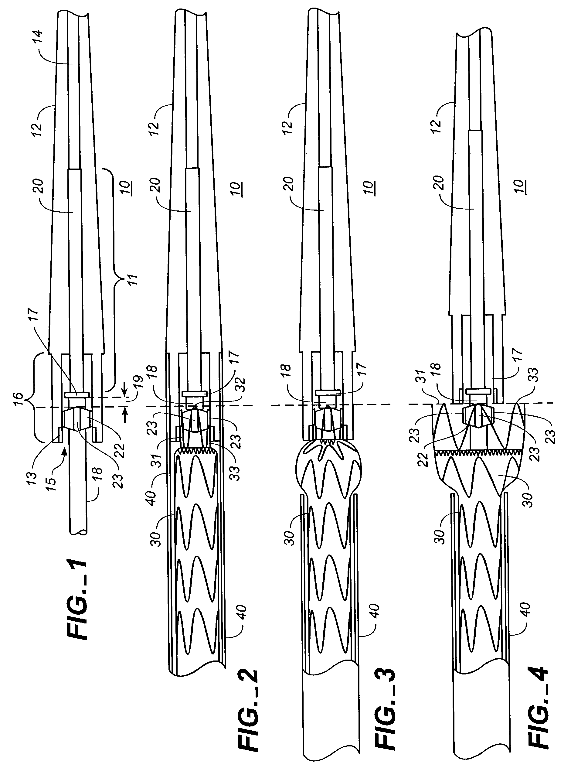
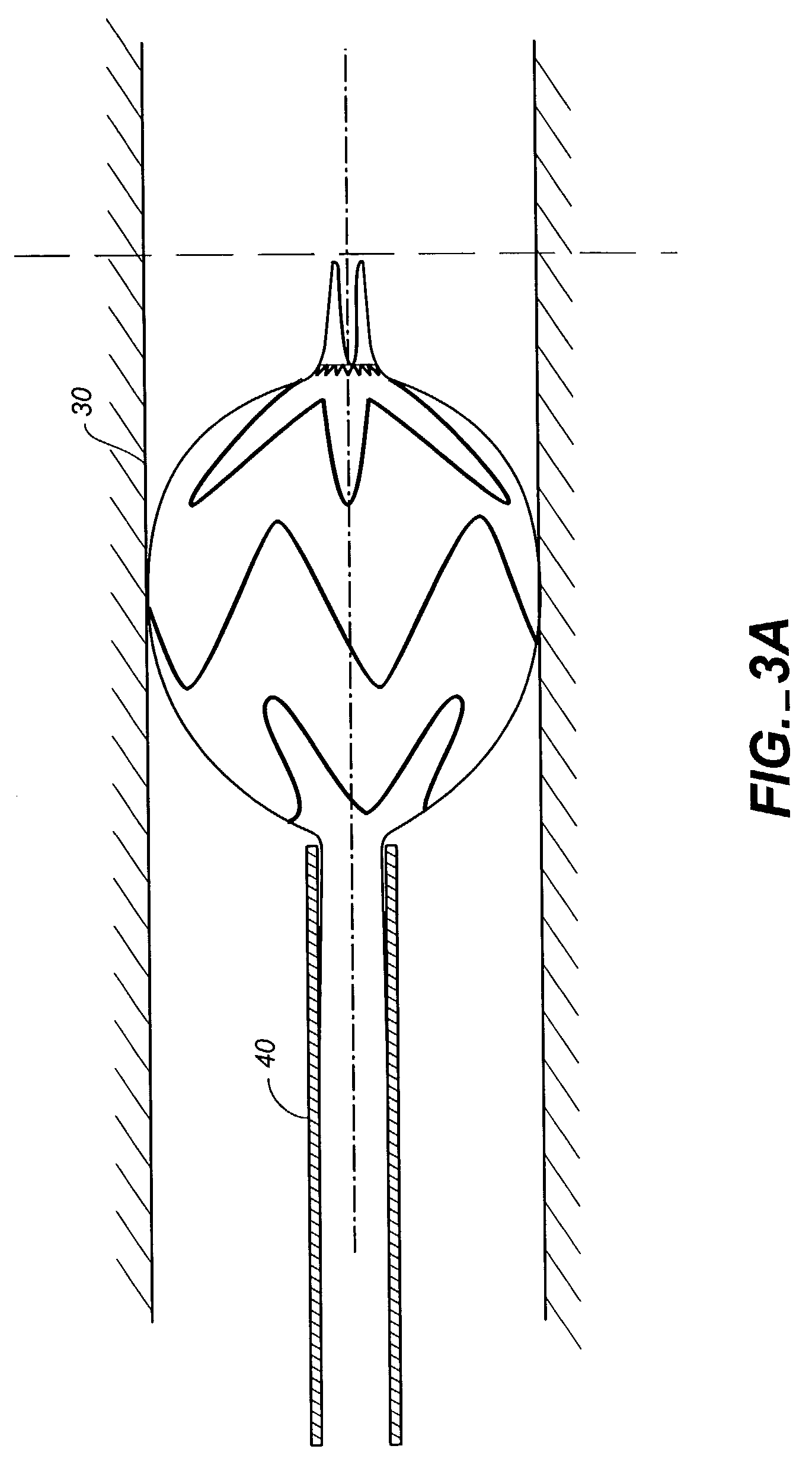
[0023]FIGS. 1-4 show portions of a stent-graft deployment delivery system 10. The vertical dashed line provides a reference line to provide correlation between the FIGS. to a common location related to the position of the end spring of the stent graft as elements of the delivery system are manipulated to at first partially deploy and then fully deploy the proximal end of the stent graft 30.

[0024]FIG. 1 illustrates the distal tapered tip portion of the delivery system 10 alone without a stent-graft while FIGS. 2-4 show close up views of the deployment delivery system tip portion loaded with a stent-graft 30, with progressive figures showing deployment from within a retractable primary sheath 40. This system could also deploy a stent alone or some other form of endoprosthesis. The subsequent use of “stent-graft” herein should be understood to include other forms of endoprosthesis.

[0025]A configuration of the stent-graft deployment system 10 includes a tapered tip 12 that is flexible a...


PUM


Abstract

A controlled stent-graft deployment delivery system (10 50 or 900) includes a stent-graft (30 or 63), a retractable primary sheath (40) containing the stent-graft in a first constrained diameter configuration, an outer tube (18) within the retractable primary sheath and within the stent-graft, and an inner tube (20) within the outer tube, where the inner tube and the outer tube both axially move relative to the retractable primary sheath and to each other. The system further includes a cap (15) coupled to a distal end of the inner tube and configured to retain at least a portion of a proximal area of the stent-graft in a radially compressed configuration. A distal assembly (100) provides controlled relative axial movement between the outer tube and the inner tube enabling the release of the proximal end (65, 67, 68, and 69) of the stent-graft from the cap and from the radially compressed configuration.

Description

RELATED APPLICATION[0001]This application is a continuation in part of provisional application Ser. No. 60 / 387,278 filed on Jun. 7, 2002 and hereby claims priority therefrom.FIELD OF THE INVENTION[0002]This invention relates generally to medical devices and procedures, and more particularly to a method and system of deploying a stent-graft in a vascular system.BACKGROUND OF THE INVENTION[0003]Prostheses for implantation in blood vessels or other similar organs of the living body are, in general, well known in the medical art. For example, prosthetic vascular grafts formed of biocompatible materials (e.g., Dacron or expanded, porous polytetrafluoroethylene (PTFE) tubing) have been employed to replace or bypass damaged or occluded natural blood vessels. A graft material supported by framework is known as a stent-graft or endoluminal graft. In general, the use of stent-grafts for treatment or isolation of vascular aneurysms and vessel walls which have been thinned or thickened by disea...

Claims


Application Information

Patent Timeline
IPC IPC(8): A61F2/04A61B17/00A61F2/06A61F2/84
CPCA61F2/95A61F2002/9665A61F2002/9505
Inventor WRIGHT, MICHAEL T.LOSTETTER, TIMOTHY W.RUIZ, ALEX
Owner MEDTRONIC VASCULAR INC
Why Eureka
Try Eureka