
Method for producing an electrical connector

a technology of electrical connectors and manufacturing methods, applied in the field of electric connectors, can solve the problems of complicated and expensive steps in the conventional methods, difficult miniaturization of electrical connectors, etc., and achieve the effect of cheap and easy manufacturing

Inactive Publication Date: 2007-09-04
JU TED
View PDF12 Cites 2 Cited by
  • Summary
  • Abstract
  • Description
  • Claims
  • Application Information

AI Technical Summary

Benefits of technology

"The present invention provides an electrical connector and a method for producing it that are cheap and easy to make. The connector has an insulative housing and a plurality of metallic wires with a part disposed inside the housing and a contact end exposed out of the housing. The method involves folding a metallic wire into a predetermined shape using upper and lower formation devices, and then using a mold to form an insulative material covering part of the wire and the contact end exposed out of it. The technical effects of this invention are that it provides a simple and cost-effective way to produce electrical connectors, which can be useful in various applications such as electronics and power systems."

Problems solved by technology

However, steps in the conventional methods are complicated and expensive and the resulting electrical connector is difficult to miniaturize.

Method used


Image

  • Method for producing an electrical connector
  • Method for producing an electrical connector
  • Method for producing an electrical connector

Examples


Embodiment Construction

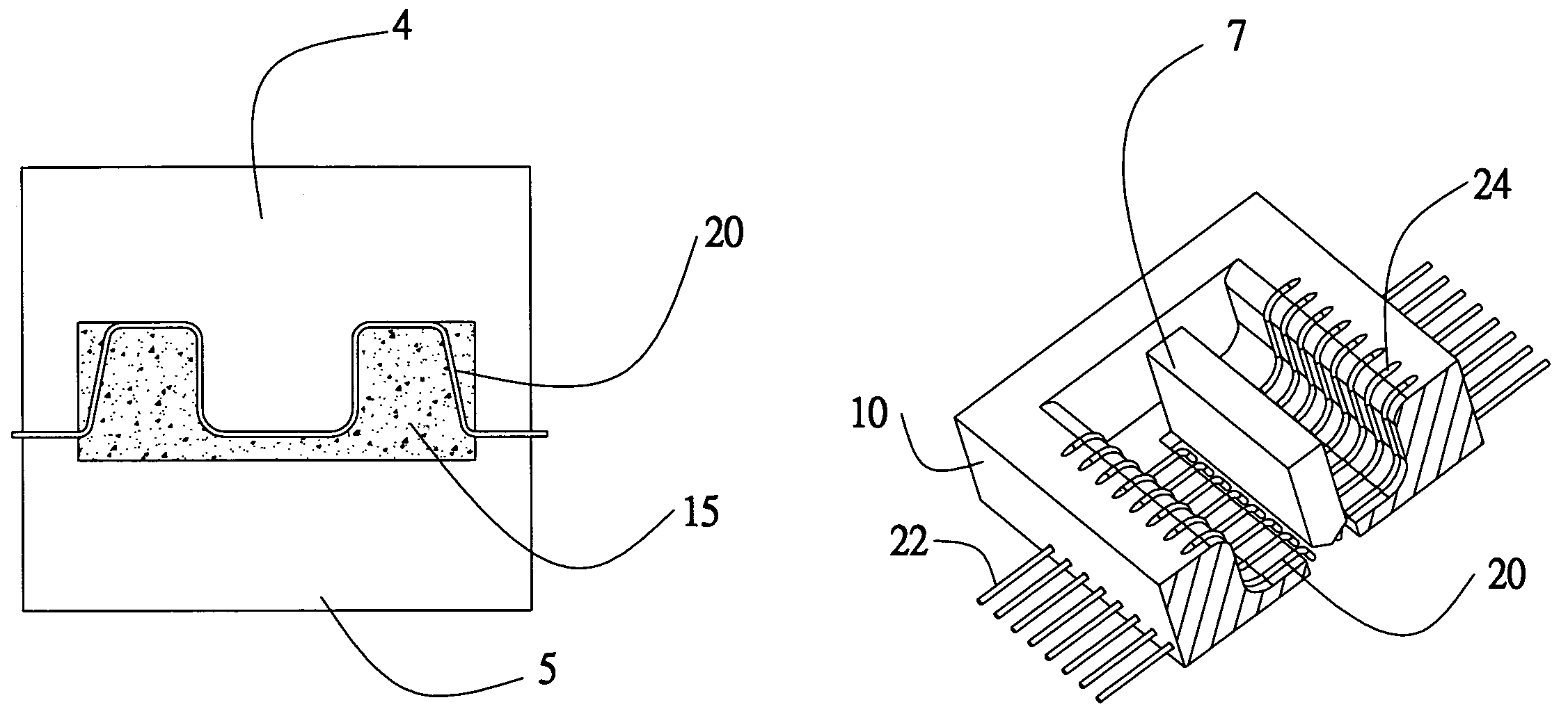
[0020]With respects to FIGS. 1 to 5, an electrical connector 1 includes an insulative housing 10 and a plurality of metallic wires 20.

[0021]The insulative housing 10 has an opening 12 and a frame round 13 circumscribes the opening 12. The metallic wire 20 has a portion disposed inside the insulative housing 10, and a contact end 21 connected to the portion, located inside the frame round 13 and extending to a top 131 of the frame round 13. The contact end 21 protrudes out of the insulative housing 10 for electrically connecting the mating member. In addition, a solder end 22 of the metallic wire 20 connected to the portion also protrudes out of a lower part of the insulative housing 10.

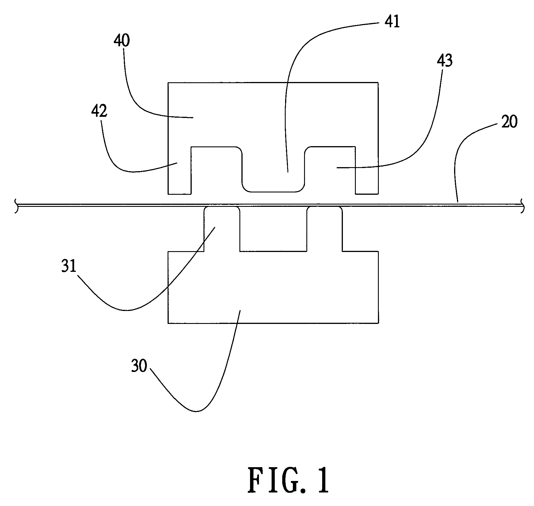
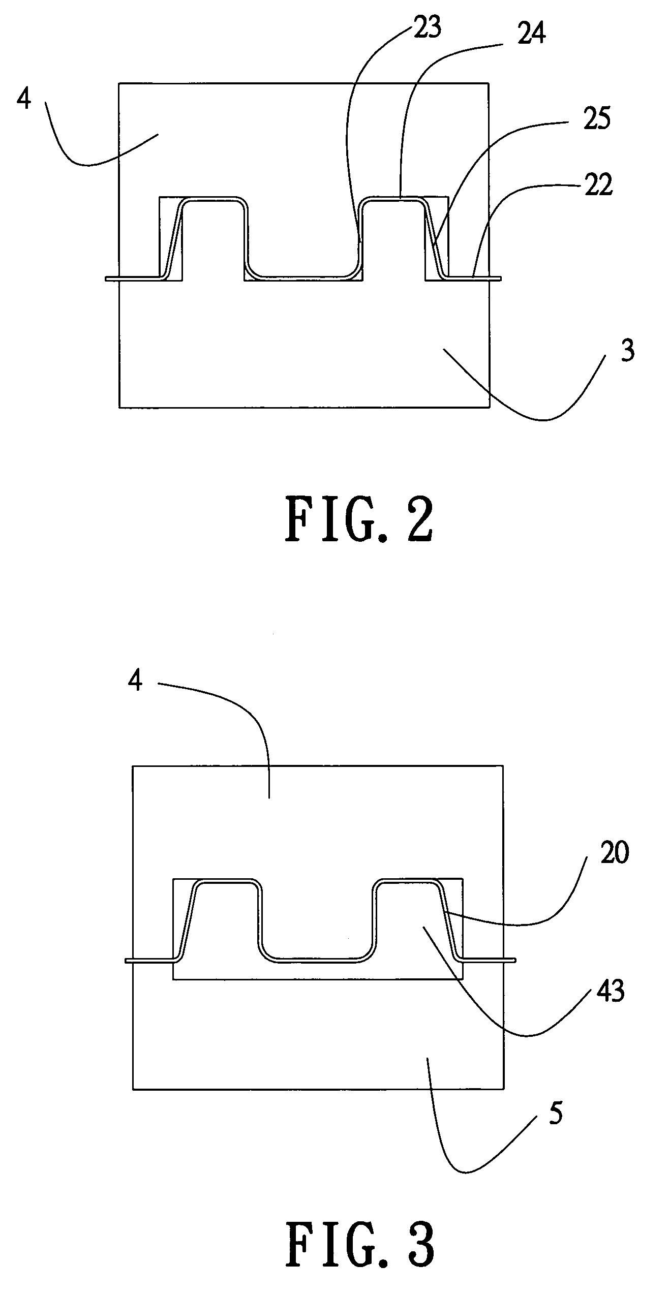
[0022]A method for producing the electrical connector 1 includes providing a lower formation device 3. Lower formation device has a base 30, substantially rectangular, two protrusion portions 31 extending from a top surface of the base 30, and a predetermined distance formed between the two protrusion...


PUM

PropertyMeasurementUnit
conductiveaaaaaaaaaa
metallicaaaaaaaaaa
shapeaaaaaaaaaa

Abstract

An electrical connector and a method for producing the same are described. A metallic wire is provided. The metallic is folded into a predetermined shape by upper and lower formation devices. One of the formation devices is replaced by a mold, and an insulative material is poured into the mold to cover part of the metallic wire and form a contact end protruding out of the insulative material. Thus, the electrical connector has an insulative housing and a plurality of metallic wires partially disposed inside the insulative housing with a contact end protruding out of the insulative housing.

Description

BACKGROUND OF THE INVENTION[0001]1. Field of the Invention[0002]The present invention relates to an electrical connector and a method for producing the same.[0003]2. Description of Related Art[0004]The conventional electrical connector, used to connect two electrical components next to each other, includes an insulative housing and a plurality of contacts disposed therein. The contacts generally are punched from metallic materials. There are two methods for arranging the contacts in the insulative housing. In one method, the punched contacts are placed in a mold, the liquid insulative material is poured into the mold, and the mold is removed after the insulative housing is cooled and set. Thus, the contacts and the insulative housing of such a conventional electrical connector are made integrally in one piece. In the second method, the contacts are directly and mechanically inserted into the insulative housing.[0005]However, steps in the conventional methods are complicated and expe...

Claims


Application Information

Patent Timeline
Patent Type & Authority Patents(United States)
IPC IPC(8): B29C45/14
CPCB29C45/14639B29C45/14221B29C45/14385B29C45/14467B29L2031/3061B29L2031/7278
Inventor JU, TED
Owner JU TED
Learn More