Lane boundary detector

Active Publication Date: 2007-09-04
TOYOTA JIDOSHA KK
View PDF11 Cites 19 Cited by
  • Summary
  • Abstract
  • Description
  • Claims
  • Application Information

AI Technical Summary

Benefits of technology

[0008]In view of the foregoing, an object of the present invention is to solve the above-described problem and provide a boundary detector which can properly distinguish a main lane and an additional lane to guide a vehicle along a proper lane.
[0014]According to the boundary detector, the candidate line of the lane boundary position drawn on the road surface is detected based on the image information acquired from the image supplied from the camera, and the lane boundary position is selected based on the candidate line of the lane boundary position. Besides, the lane boundary position of the additional lane that is added to the main lane is selected. Upon selecting the lane boundary position of the additional lane, the boundary detector stops adopting the lane boundary position selected by one of the lane boundary position selecting unit and the additional lane boundary position selecting unit over the predetermined time period. Thus, since the boundary detector stops adopting the selected lane boundary position over the predetermined time period when the lane boundary position of the additional lane is selected, the boundary detector can properly distinguish the main lane from the additional lane to guide the vehicle along the correct lane without being affected by the lane boundary position of the additional lane, whereby a continuous and appropriate driving of the vehicle is allowed.

Problems solved by technology

Above described two patent applications do not particularly disclose techniques to prevent such inconvenience and therefore are not immune to detection error of the white lines delineating the lanes.

Method used


Image

  • Lane boundary detector
  • Lane boundary detector
  • Lane boundary detector

Examples


Embodiment Construction

[0025]In the following, an exemplary embodiment of a boundary detector according to the present invention is described in detail with reference to the accompanying drawings. The present invention is not limited by the embodiment.

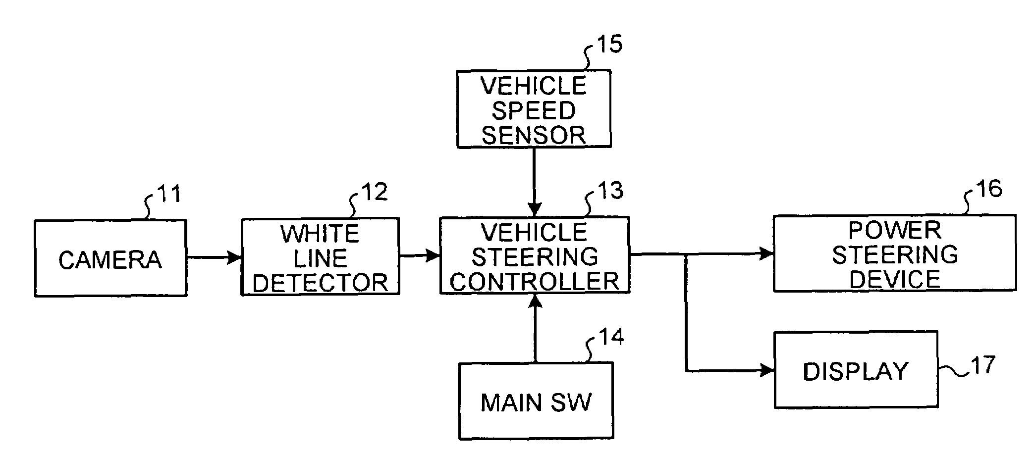
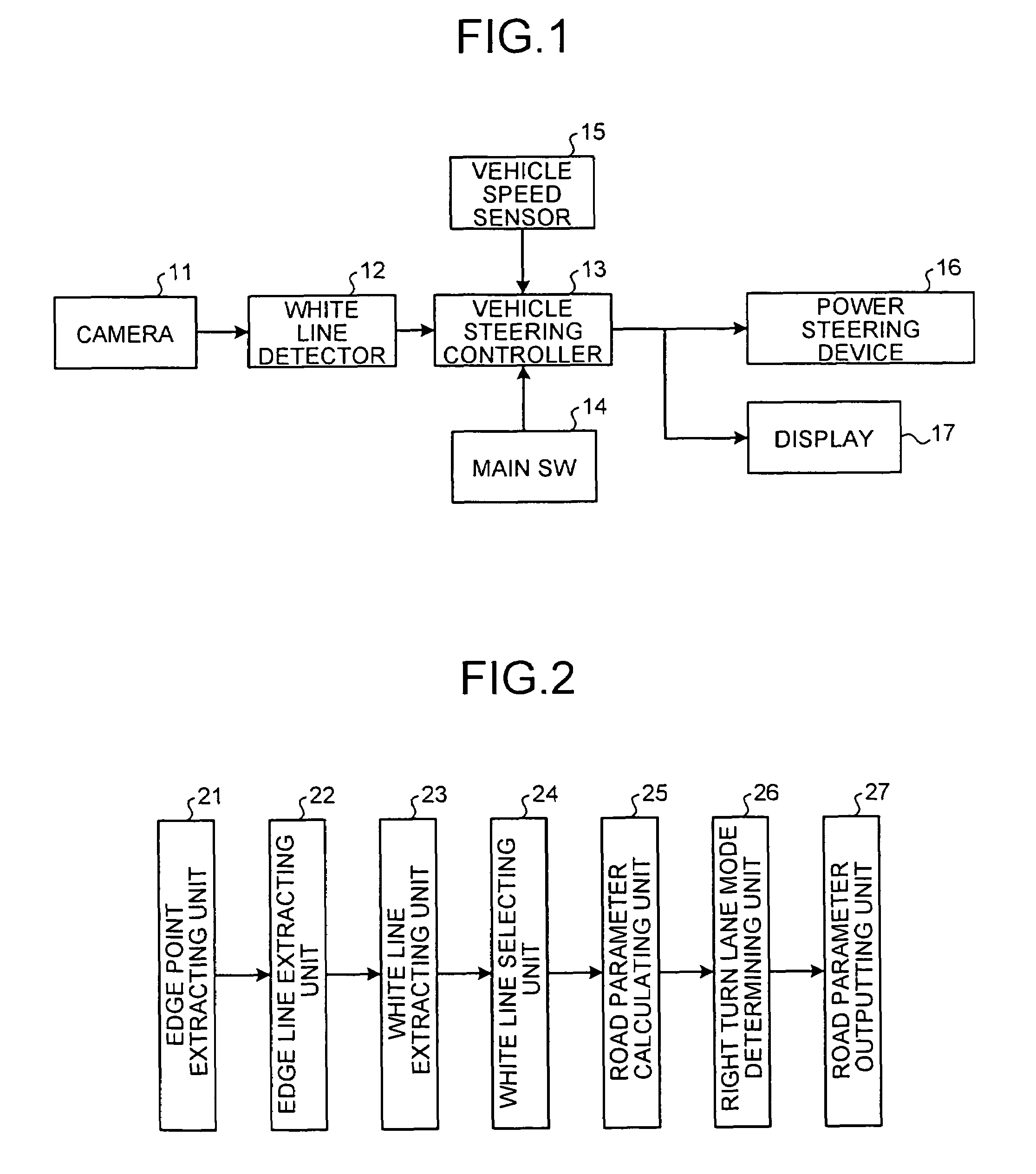
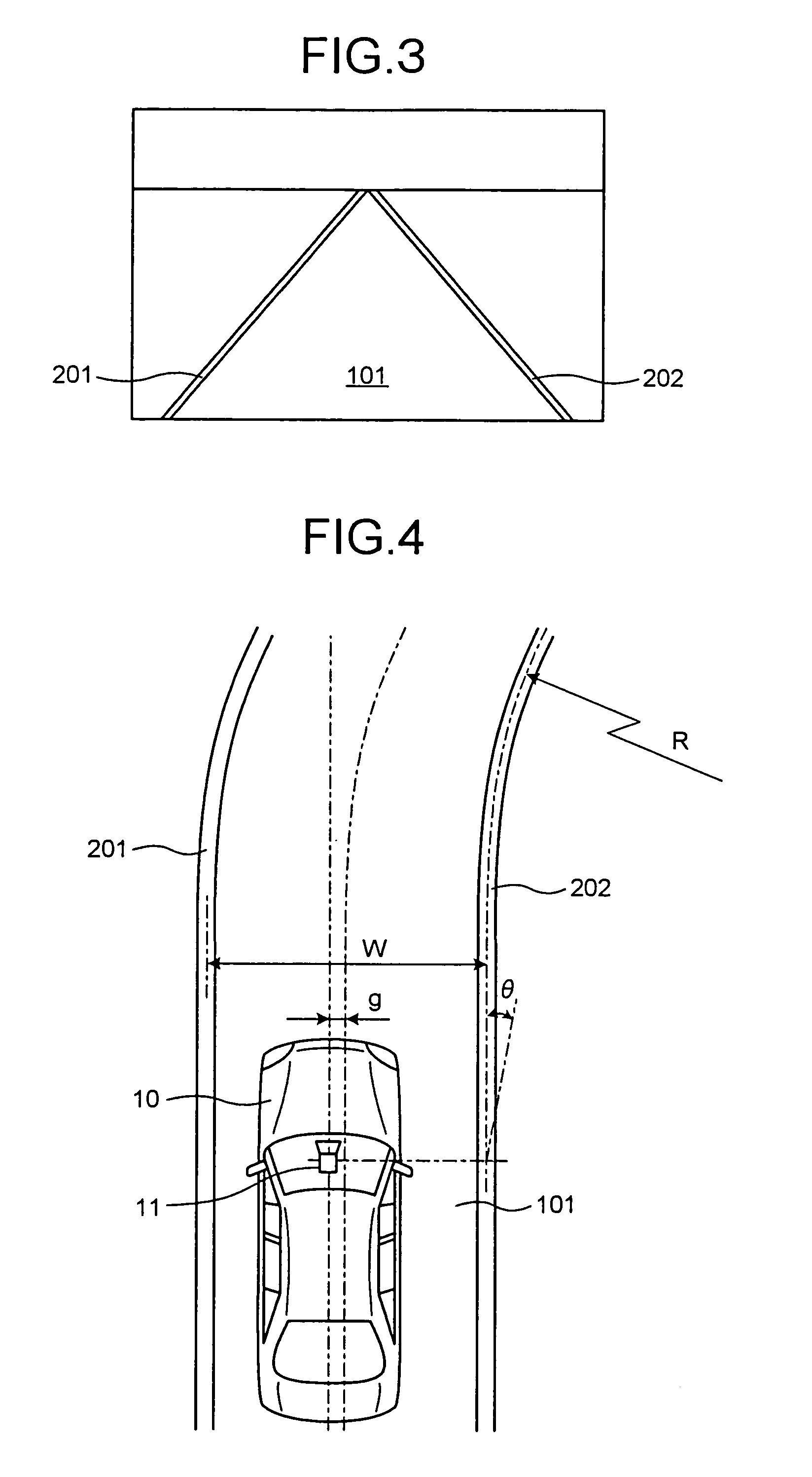
[0026]FIG. 1 is a block diagram of a structure of a vehicle controller to which a boundary detector according to the embodiment of the present invention is applied, FIG. 2 is a block diagram of a structure of the boundary detector of the embodiment, FIG. 3 is a schematic diagram of an image picked up by a camera, FIG. 4 is a schematic diagram of road parameters which are supplied as outputs from the boundary detector of the embodiment, FIG. 5 is a plan view of a road including a main lane and an right turn lane, FIG. 6A is a schematic diagram of the main lane after an image processing, FIG. 6B is a schematic diagram of an additional section of the main lane after the image processing, FIG. 7 is a flowchart of a boundary detection control by the boundary dete...


PUM


Abstract

A boundary detector includes a candidate line detecting unit that detects a candidate line of a lane boundary position drawn on the road surface based on image information from a camera. The detector also includes a lane boundary position selecting unit that selects the lane boundary position based on the candidate line; an additional lane boundary position selecting unit that selects a lane boundary position of an additional lane that is added to a main lane based on the candidate line; and an additional processing unit that stops adopting the lane boundary position for a predetermined time period when the additional lane boundary position selecting unit selects a lane boundary position of the additional lane.

Description

BACKGROUND OF THE INVENTION[0001]1. Field of the Invention[0002]The present invention relates to a boundary detector and a boundary detecting method that acquire image information based on an image supplied from a camera that is mounted on a vehicle and picks up an image of a road surface, and detect a boundary drawn on the road surface based on the acquired image information.[0003]2. Description of the Related Art[0004]In recent years, an apparatus has been developed for picking up an image of a road surface in front of a vehicle with a camera, detecting a boundary, i.e., a white line, drawn on the road surface based on the image picked up by the camera, and automatically driving the vehicle on a lane delineated by the white line. For the realization of automatic driving, the lane must be properly detected, in other words, a detector is required for processing the image picked up by the camera to detect the lane, i.e., the white lines. Such detectors are disclosed in Japanese Paten...

Claims


Application Information

Patent Timeline
Patent Type & Authority Patents(United States)
IPC IPC(8): B60Q1/00B60R21/00B60Q1/34B60R1/00G05D1/02G06T1/00G06T7/60G08G1/16
CPCB60Q1/34B60Q1/346G05D1/0246G06K9/00798G08G1/161G08G1/167G05D2201/0213G06V20/588
Inventor NISHIDA, MAKOTOWATANABE, AKIHIRO
Owner TOYOTA JIDOSHA KK
Why Eureka
Try Eureka