Method and apparatus for processing hard material
Inactive Publication Date: 2007-09-11
LASER ABRASIVE TECH LLC
View PDF41 Cites 13 Cited by
- Summary
- Abstract
- Description
- Claims
- Application Information
AI Technical Summary
Benefits of technology
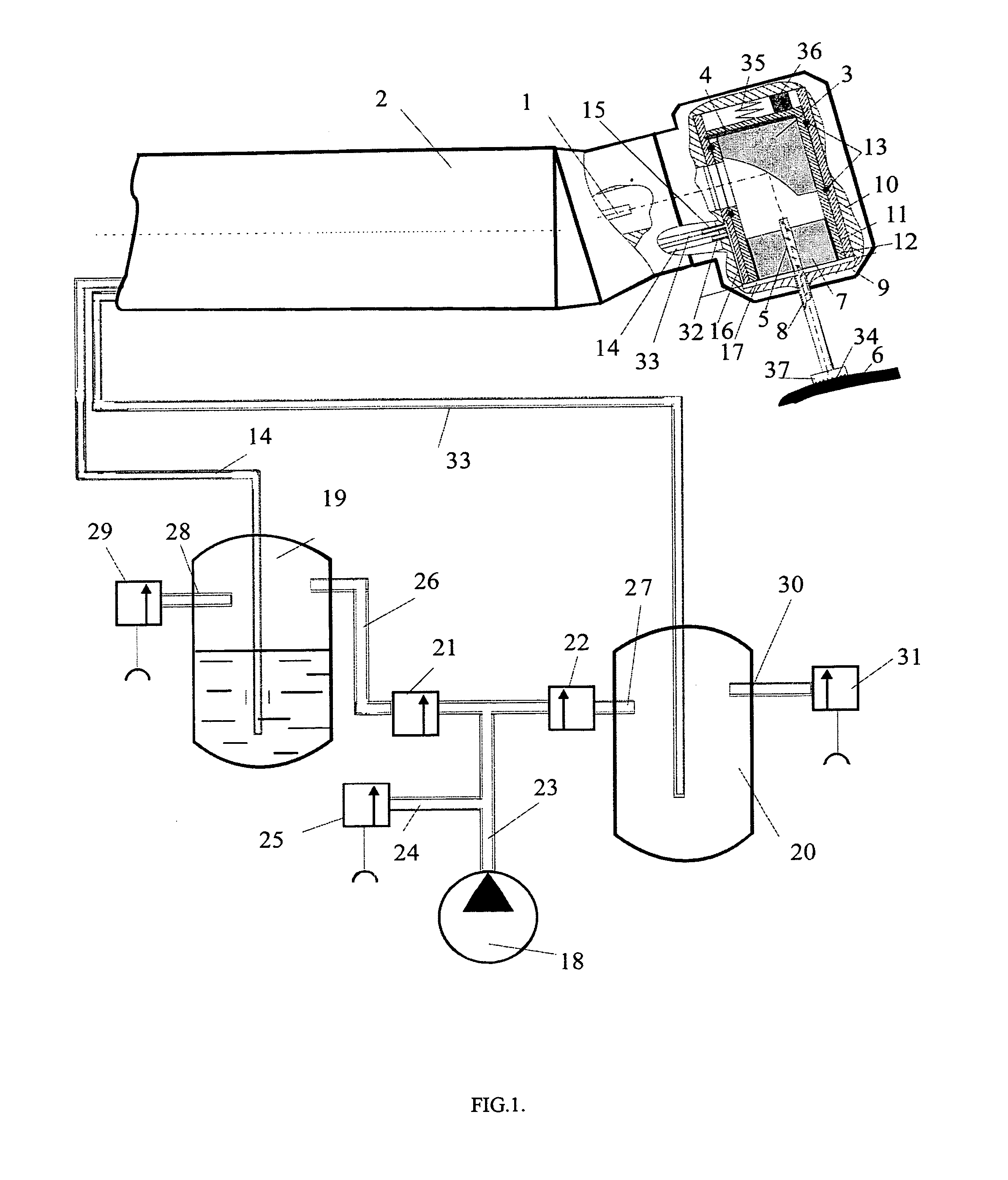
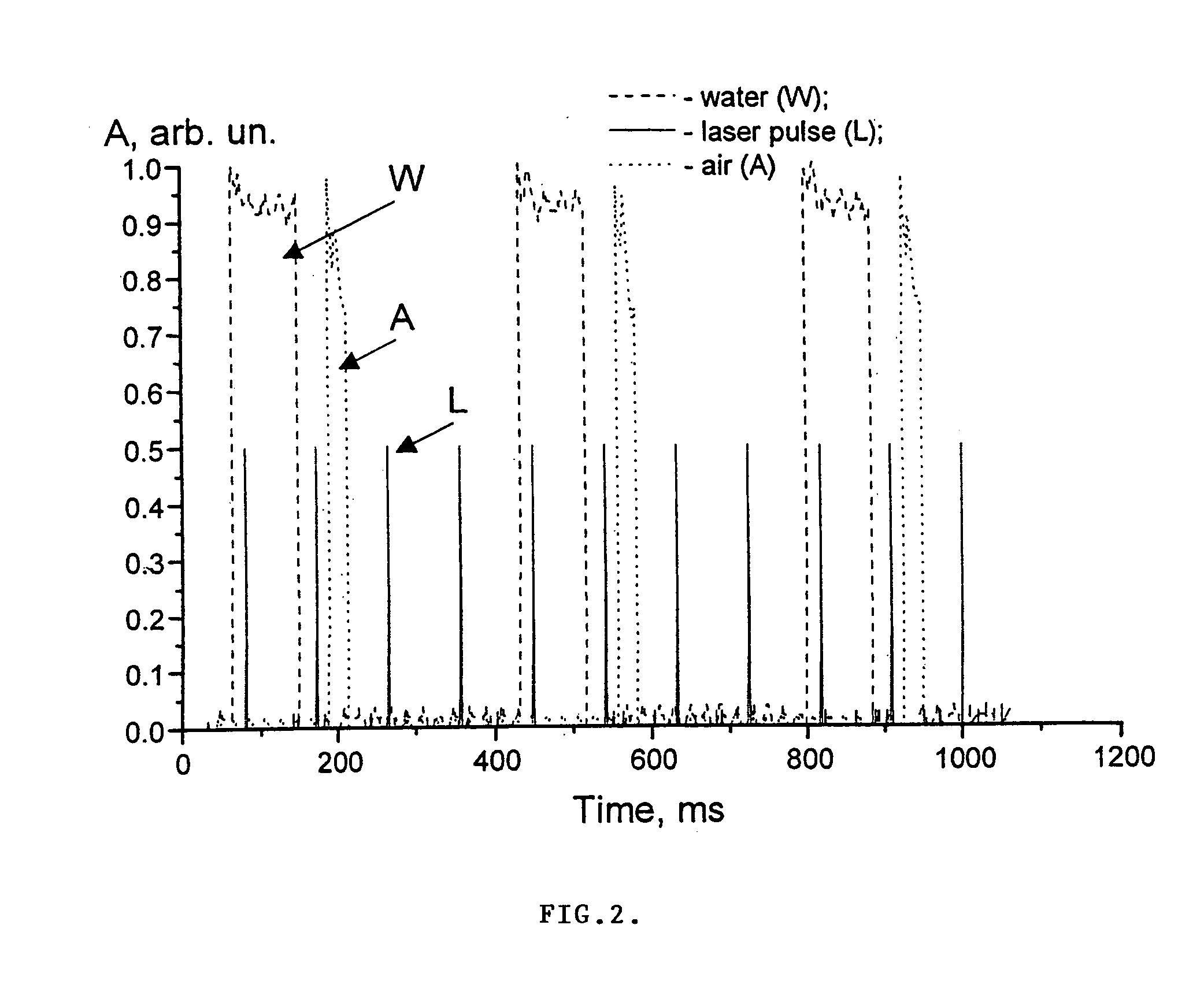
[0007]In accordance with the above, this invention provides a method and apparatus for processing a hard material with optical radiation from a suitable source. The radiation is applied through a tip to a surface in a treatment zone of the material, and the treatment zone is cleaned by a suitable mechanism of dirt, including products of ablation. The tip is slightly spaced from the material surface during at least most of the time a gas, such as air, is applied by a suitable mechanism to the surface for the cleaning thereof. A hydrating fluid such as water may also be applied by a suitable mechanism to the treatment zone, the tip through which radiation is applied being slightly spaced from the surface of the material during at least a portion of the time the hydrating fluid is being applied. The thickness of a water layer formed by the hydrating fluid on the treatment surface is limited to prevent radiation energy loss. The radiation may be applied as a sequence of pulses at a selected repetition rate, with the gas being applied during intervals between at least selected ones of the radiation pulses. The hydrating fluid may also be applied at least in part between at least selected ones of the radiation pulses. The applying of the hydrating fluid may be followed by the applying of the gas between the same radiation pulses, the hydrating fluid and the gas may be applied during different intervals between pulses or the applying of hydrating fluid may overlap with at least selected ones of the radiation pulses.
[0010]Particles of ablation and other energy from the ablation may be returned to the treatment surface to enhance the efficiency of the ablation by a reflector or other suitable mechanism.
Problems solved by technology
The thickness of a water layer formed by the hydrating fluid on the treatment surface is limited to prevent radiation energy loss.
Method used
View moreImage
Smart ImageViewing Examples
Examples
second embodiment
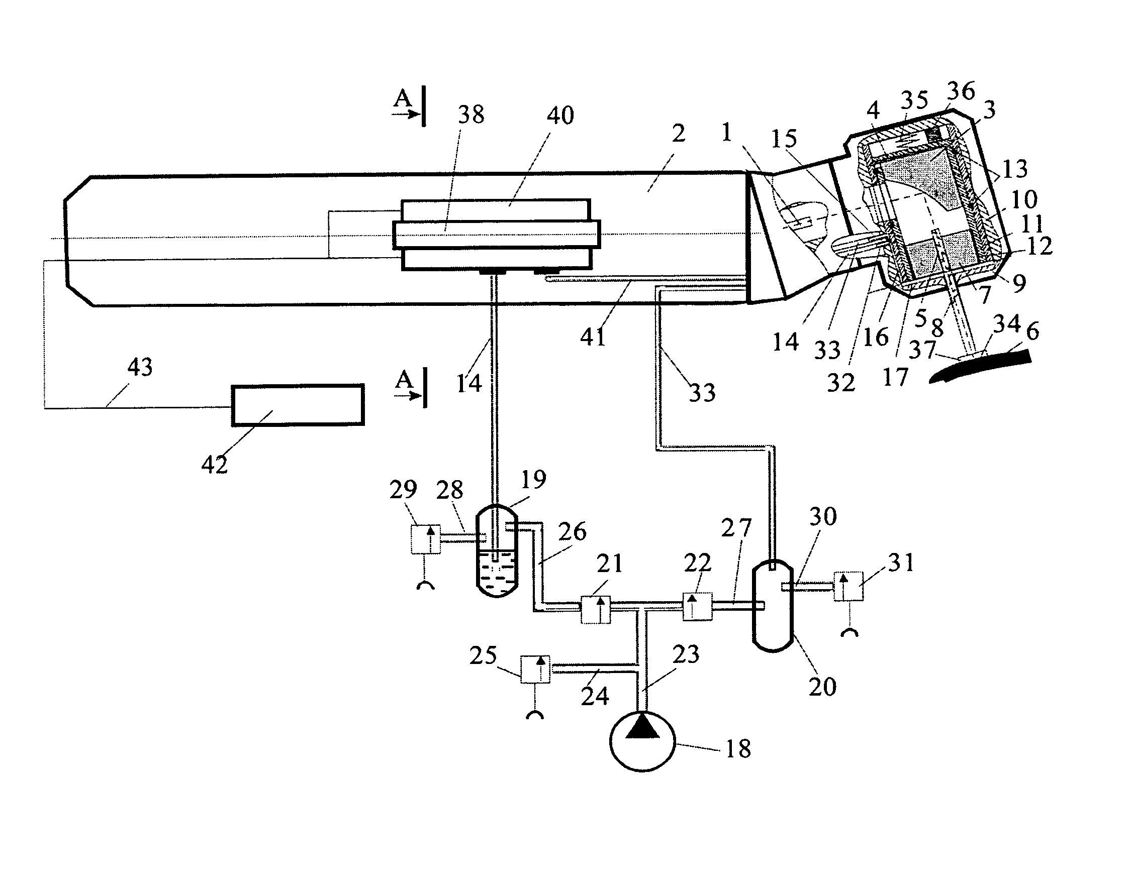
[0015]FIG. 3 is a partially cut-away illustration of apparatus in accordance with the invention.
[0016]FIG. 3A is a sectional view taken along the line A-A in FIG. 3.
third embodiment
[0017]FIG. 4 is a partially cut-away illustration of apparatus in accordance with the invention.
fourth embodiment
[0018]FIG. 5 is a partially cut-away illustration of apparatus in accordance with the invention.
Login to View More PUM
 Abstract
A method and apparatus are provided for processing a hard material, for example a hard biological material such as dental enamel or bone, with optical radiation. A treatment zone of the material is selectively cleaned of ablation products and other dirt to enhance processing efficiency, and a tip through which the optical radiation is applied to the treatment zone of the hard material is spaced slightly from the treatment zone during at least a portion of the time that hydrating fluid is being applied to the zone and / or while air or another gas is applied to the zone to clean the surface thereof.
Description
RELATED APPLICATION[0001]This application claims priority under 35 U.S.C. § 119(e) to U.S. Provisional Application Ser. No. 60 / 371,097, filed on Apr. 9, 2002, which is herein incorporated by reference in its entirety.FIELD OF THE INVENTION[0002]This invention relates to the processing of hard material, and more particularly to the processing of such material with optical radiation.BACKGROUND OF THE INVENTION[0003]Hard material such as a metal, dental material, such as filling material or dental prosthesis material, or a hard bio-tissue, for example tooth enamel dentine or bone, has heretofore been ablated or otherwise processed by directing optical radiation, and in particular, laser radiation, at the material. However, the inventors have found that such procedures have in the past been less optimally efficient for a number of reasons.[0004]In particular, where a laser, for example an Er laser, is being used to ablate bio-tissue such as tooth enamel, the efficiency of the ablation c...
Claims
Login to View More Application Information
Patent Timeline
 IPC IPC(8): A61B18/18A61C1/00A61B18/00A61B18/22A61C17/02
CPCA61B18/22A61C1/0046A61B2218/006A61C17/0217A61B2018/00005
Inventor ALTSHULER, GREGORY B.BELIKOV, ANDREI V.
Owner LASER ABRASIVE TECH LLC
Features
- R&D
- Intellectual Property
- Life Sciences
- Materials
- Tech Scout
- Unparalleled Data Quality
- Higher Quality Content
- 60% Fewer Hallucinations
Learn More Browse by: Latest US Patents, China's latest patents, Technical Efficacy Thesaurus, Application Domain, Technology Topic, Popular Technical Reports.
© 2025 PatSnap. All rights reserved.Legal|Privacy policy|Modern Slavery Act Transparency Statement|Sitemap|About US| Contact US: help@patsnap.com


