Overlapping common-path interferometers for two-sided measurement

a technology of interferometers and common paths, applied in the direction of interferometers, instruments, measurement devices, etc., can solve the problems of affecting the accuracy of interferometers. , to achieve the effect of reducing the cost of interferometers, and reducing the accuracy of interferometers

Inactive Publication Date: 2007-09-11
CORNING INC
View PDF9 Cites 14 Cited by
  • Summary
  • Abstract
  • Description
  • Claims
  • Application Information

AI Technical Summary

Benefits of technology

[0006]As such, the invention extends the precision of optical interferometry beyond the ordinary field of view of a single interferometer for achieving three-dimensional representations of opaque test parts. The opposite sides of the test parts having opaque surfaces can be individually measured to the customary precision of conventional phase-shifting interferometers and can be related to each other with similar precision for making comparative measurements. The measurement of the reference surfaces preferably takes place simultaneously with the two measurements of the opposite side surfaces of the opaque test parts to avoid time-sensitive calibration errors. As a result, the measurements can be taken in production environments or other non-laboratory environments and can accommodate a range of positioning and alignment errors, because the measurements of the reference surfaces provide automatic self-calibration for the overlapping interferometers. Any changes to the spacing or orientation of the reference surfaces can be measured simultaneously with the measurements of the opposite side surfaces.
[0017]Alternatively, a beamsplitter can be used that divides the light source into the first and second measuring beams and redirects the reflected first and second measuring beams to the imaging subsystem. The beamsplitter is preferably a polarizing beamsplitter and works in conjunction with a first polarization modifying element located between the beamsplitter and the first reference surface for redirecting the reflected first measuring beam to the imaging subsystem and a second polarization modifying element located between the beamsplitter and the second reference surface for redirecting the reflected second measuring beam to the imaging subsystem. The polarization modifying elements preferably provide for cumulative polarization rotation for directing reflected portions of the first and second measuring beams to the imaging subsystem and for preventing other portions of the first and second measuring beams that transmit through both reference surfaces from reaching the imaging subsystem. The beamsplitter can be a first of two beamsplitters. The second beamsplitter directs the reflected first measuring beam to a first camera and directs the reflected second measuring beam to a second camera.

Problems solved by technology

The measurement of opposite side surfaces of opaque parts is difficult to accomplish using conventional interferometry, particularly for purposes of both measuring the two sides individually, such as for determining flatness of each, and measuring the two sides relative to each other, such as for determining parallelism and thickness.
However, surface irregularities, whose determination are among the actual purposes of the measurement, and foreign contaminants can distort the comparative measurements.
Each interferometer has its own reference surface, and the calibration of the two reference surfaces with the optical flat over measurements taken at different times and under different conditions adds considerable complexity and opportunity for error.

Method used


Image

  • Overlapping common-path interferometers for two-sided measurement
  • Overlapping common-path interferometers for two-sided measurement
  • Overlapping common-path interferometers for two-sided measurement

Examples


Embodiment Construction

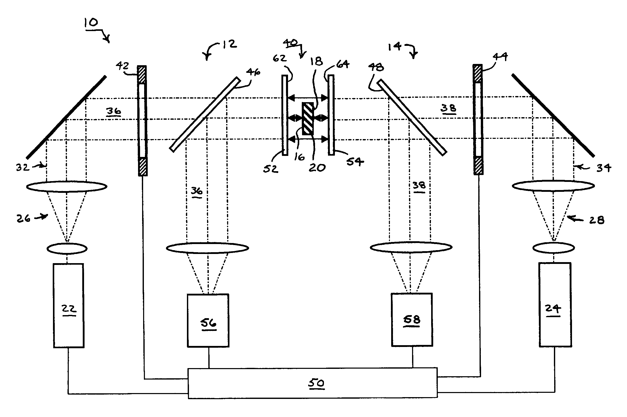
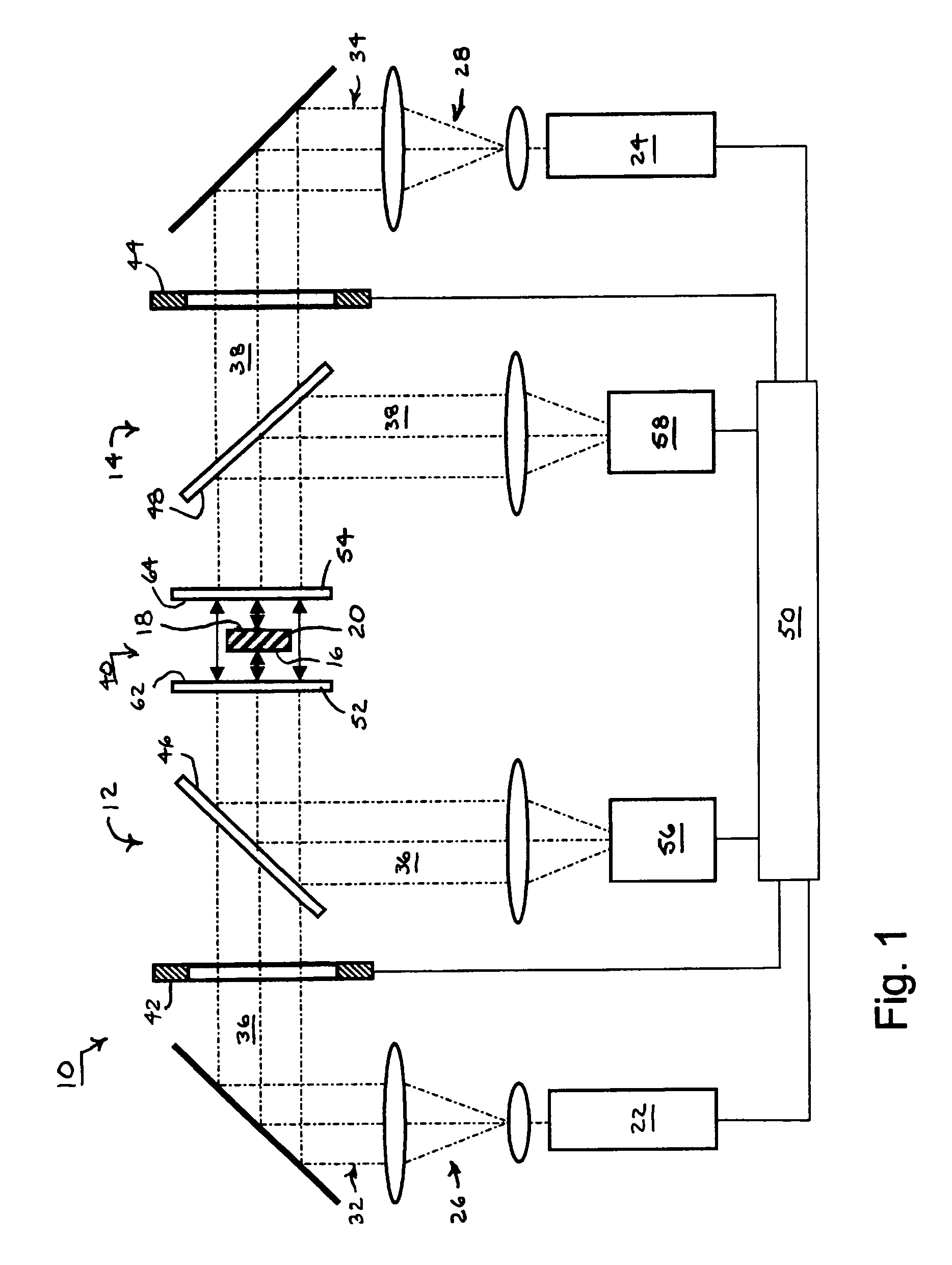
[0040]An interferometric measuring system 10 combining first and second common-path interferometers 12 and 14 for measuring opposite first and second sides 16 and 18 of an opaque test part 20 appears in FIG. 1. The opaque test part 20 can be a part that is made of materials that are not transmissive within the range of frequencies propagated by the common-path interferometers or that is sufficiently diffuse to preclude the ordered transmission of such frequencies. The first and second interferometers 12 and 14 include respective first and second light sources 22 and 24 and first and second beam shapers 26 and 28. The first and second light sources 22 and 24 are preferably frequency-tunable light sources for producing respective first and second measuring beams 32 or 34 that can be varied through a succession of different wavelengths for carrying out frequency-shifting interferometry. The first and second beam shapers 26 and 28 preferably include beam expanders and collimators for es...


PUM


Abstract

Two common-path interferometers share a measuring cavity for measuring opposite sides of opaque test parts. Interference patterns are formed between one side of the test parts and the reference surface of a first of the two interferometers, between the other side of the test parts and the reference surface of a second of the two interferometers, and between the first and second reference surfaces. The latter measurement between the reference surfaces of the two interferometers enables the measurements of the opposite sides of the test parts to be related to each other.

Description

TECHNICAL FIELD[0001]Two-sided measurement of opaque parts, including part assemblies, by interferometers involves separately measuring the two sides and relating the separate measurements to each other for making comparisons between the two sides. Part parameter comparisons include three-dimensional form, profile, flatness, parallelism, and thickness.BACKGROUND OF THE INVENTION[0002]The measurement of opposite side surfaces of opaque parts is difficult to accomplish using conventional interferometry, particularly for purposes of both measuring the two sides individually, such as for determining flatness of each, and measuring the two sides relative to each other, such as for determining parallelism and thickness. For example, separate interferometers can be used to measure the two sides individually for determining flatness, but each is a relative measure unrelated to the other. Interferometers including combinations of mirrors have been used to measure the two sides simultaneously...

Claims


Application Information

Patent Timeline
Patent Type & Authority Patents(United States)
IPC IPC(8): G01B11/02
CPCG01B11/06G01B11/2441G01B11/306G01B9/02028G01B9/02021G01B9/02027G01B2290/45G01B9/02G01B11/02
Inventor KULAWIEC, ANDREW W.TRONOLONE, MARK J.DUNN, THOMAS J.MARRON, JOSEPH C.
Owner CORNING INC
Why Eureka
Try Eureka