
Air bed with stable supporting structure

a technology of supporting structure and air bed, which is applied in the direction of beds, fluid mattresses, couches, etc., can solve the problems of user falling off, one side of the air bed is liable to rise or even turn, and the stability of the air bed is not sufficient, so as to achieve simple structure, beautiful appearance, and satisfactory stability

Active Publication Date: 2007-09-18
BESTWAY USA A CORP OF DELAWARE
View PDF7 Cites 21 Cited by
  • Summary
  • Abstract
  • Description
  • Claims
  • Application Information

AI Technical Summary

Benefits of technology

The design provides excellent stability, prevents tipping, reduces production costs, and offers a visually appealing structure without protruding features that could cause injuries.

Problems solved by technology

However, a conventional air bed has a lightweight and a height higher than an air mattress; therefore, it is not sufficiently stable.
Hence, when a user lies or sits on an edge of the air bed, one side of the air bed is liable to rise or even turn over, and the user may fall off.
Although these two kinds of air beds can be kept in a stable state and the possibility of their turning over can be decreased, they have three drawbacks: (i) the air stabilizing bars and the stabilizing ring are provided around the periphery of the air bed at its bottom and have a larger volume, and this may cause a user, especially an elderly person or a child, to tread onto a protrusive air stabilizing bar or stabilizing ring and fall off, resulting in an injury; (ii) the two kinds of air beds mentioned above have a complicated structure, which would decrease production efficiency and increase production costs; and (iii) the air beds do not have a very beautiful appearance.

Method used


Image

  • Air bed with stable supporting structure
  • Air bed with stable supporting structure
  • Air bed with stable supporting structure

Examples


Embodiment Construction

[0016]The preferred embodiment of the present invention will be described further in detail with reference to the accompanying drawings.

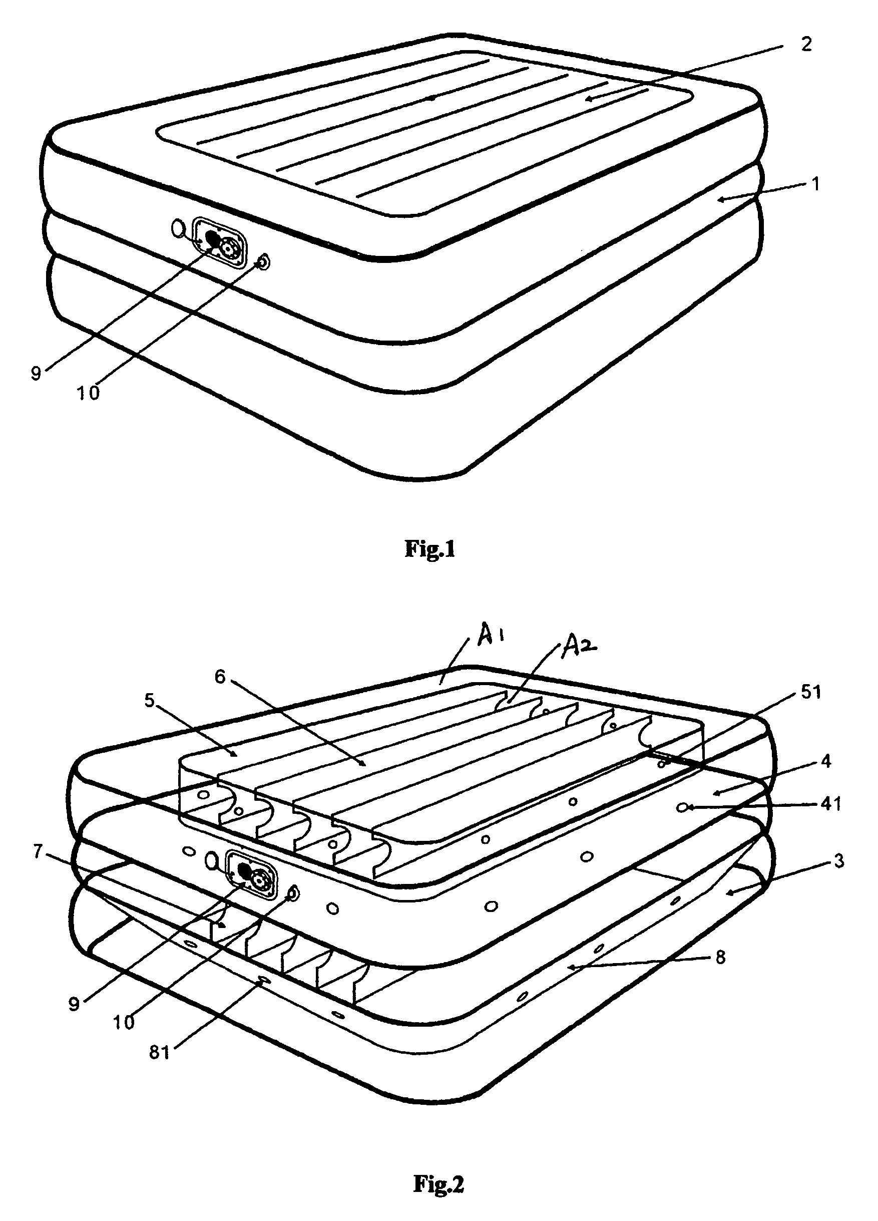
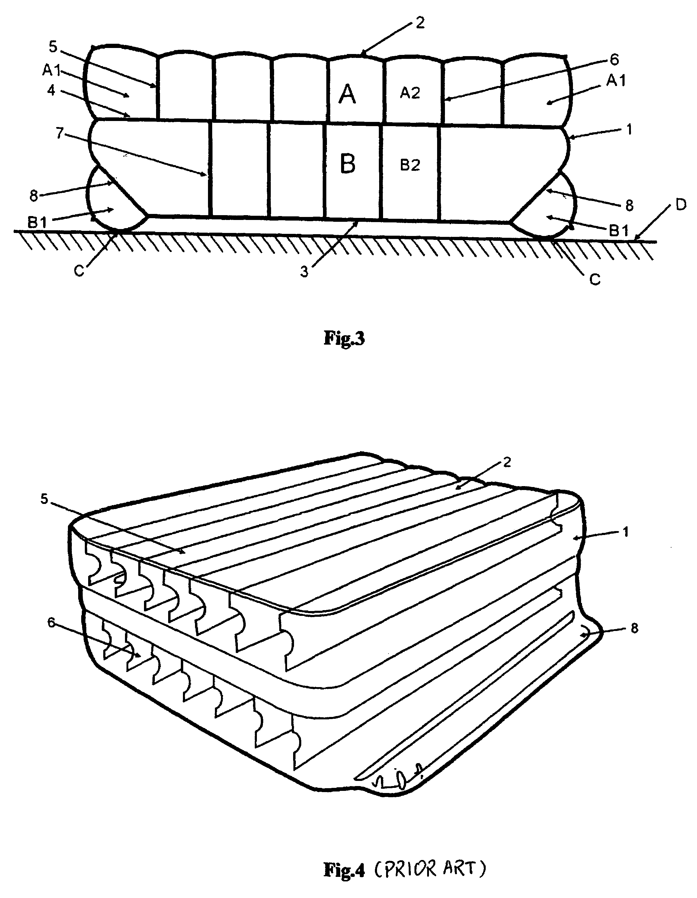
[0017]As shown in FIGS. 1, 2, and 3, the air bed of the invention may comprise a periphery sheet 1, a top sheet 2, a bottom sheet 3, and a middle sheet 4. The upper edge of periphery sheet 1 is welded to the edge of top sheet 2. The lower edge of periphery sheet 1 is welded to the edge of bottom sheet 3, middle sheet 4 is provided between top sheet 2 and bottom sheet 3 and is welded to the middle portion of periphery sheet 1, which separates the air bed into an upper air-chamber A and a lower air-chamber B. Air holes 41 are provided on the middle sheet 4 to communicate upper air-chamber A with lower air-chamber B. A loop of an outer extending strip 5 is provided in the upper air-chamber A to separate upper air-chamber A into a peripheral air-chamber A1 and an upper main air-chamber A2. A first set of extending strips 6, which extends from one end of...


PUM


Abstract

An air bed with a stable supporting structure comprises a periphery sheet, a top sheet, and a bottom sheet. A middle sheet separates the air bed into an upper air-chamber and a lower air-chamber, an outer extending strip separates the upper air-chamber into a peripheral air-chamber and an upper main air-chamber, a first set of extending strips is provided in the upper main air-chamber, a second set of extending strips, which is welded to the middle sheet and the bottom sheet, is provided in the lower air-chamber, and an oblique extending strip is provided around the periphery of the second set of extending strips and is welded with the periphery sheet and the bottom sheet to separate the lower air-chamber into a lower main air-chamber and a peripheral auxiliary air-chamber. The lower main air-chamber is a space which has a shape of an inverse cone and receives air therein. Its outer surface is concave with respect to the outer surface of the peripheral auxiliary air-chamber, that is, the surface of the peripheral auxiliary air-chamber extends beyond the surface of the bottom sheet of the lower main air-chamber.

Description

BACKGROUND OF THE INVENTION[0001]The present invention relates to an air bed that may be used for family or camping, and more specifically, to an air bed with a stable supporting structure.[0002]An air bed, which can be carried and easily stored, and which can be very comfortable and enjoyed by a user, is becoming more and more popular. This kind of air bed not only may be used as a spare bed for a visitor or a friend, but it also may be used for camping. However, a conventional air bed has a lightweight and a height higher than an air mattress; therefore, it is not sufficiently stable. Hence, when a user lies or sits on an edge of the air bed, one side of the air bed is liable to rise or even turn over, and the user may fall off. In order to solve the problem, some improvements need to be made to the air bed.[0003]As shown in FIG. 4 and FIG. 5, a conventional air bed may comprise a periphery sheet 1, a top sheet 2, a bottom sheet 3, a middle sheet 4, a parallel extending strip set ...

Claims


Application Information

Patent Timeline
Patent Type & Authority Patents(United States)
IPC IPC(8): A47C27/08A47C27/10
CPCA47C27/082A47C27/087A47C27/10
Inventor LIU, FENG
Owner BESTWAY USA A CORP OF DELAWARE
Learn More