Torque measuring device for rotating body

a technology of rotating bodies and measuring devices, which is applied in the direction of measurement devices, instruments, directional drilling, etc., can solve the problems of low impact resistance, difficult to modify the material and configuration of difficult to use ferrite for the hollow circular cylinder, so as to improve the transmission efficiency and yield large output. , the effect of improving the transmission efficiency

Active Publication Date: 2007-09-18
MINEBEAMITSUMI INC
View PDF5 Cites 5 Cited by
  • Summary
  • Abstract
  • Description
  • Claims
  • Application Information

AI Technical Summary

Benefits of technology

[0025]The present invention has been made in light of the above problems, and it is an object of the present invention to provide a torque measuring device for a rotating body, in which transmission efficiency is improved between a primary coil and a secondary coil of a rotary transformer to supply electric power from a stationary section to a rotary section.
[0026]In order to achieve the object described above, according to an aspect of the present invention, there is provided a torque measuring device for a rotating body, which includes: a stationary section; a rotary section; and a rotary transformer composed of a primary coil disposed at the stationary section, and a secondary coil disposed at the rotary section, wherein an electric power is transmitted from the stationary section to the rotary section by electromagnetic induction, a torque generated at a rotating body is detected at the rotary section by means of the electric power transmitted, and wherein a detection result is transmitted from the rotary section to the stationary section, and the torque measuring device for a rotating body further includes a capacitor connected at a side of the secondary coil of the rotary transformer, and a series resonant circuit is formed by the capacitor in combination with a leakage inductance of the rotary transformer. Consequently, a large output can be efficiently yielded at the secondary coil side thus improving transmission efficiency from the stationary section to the rotary section, which results in a reduced number of turns on the secondary coil and an enhanced reliability of the torque measuring device for a rotating body.
[0027]In the aspect of the present invention, the capacitor connected at the side of the secondary coil may be a variable capacitor. Consequently, the capacitor can be easily adjusted for a resonance point when the joint member at the driving side jointed to the outer side of the driving side flange is subjected to change, whereby the torque measuring device for a rotating body can be flexibly used.

Problems solved by technology

Ferrite, however, has a low impact resistance and therefore invites a serious problem with reliability in strength, for example, fracture due to the second coil 117 expanding during the rotation of the rotary section, which makes it difficult to use ferrite for the hollow circular cylinder 100.
Accordingly, the transmission efficiency is normally improved by modifying the configuration of the rotary section functioning as a magnetic core, and by adjusting the number of turns on the coils, but the restrictions by applications and usage environments make it difficult to modify the material and configuration of the hollow circular cylinder 100.
However, increasing the number of turns on the secondary coil 117 leads to an increased weight of the rotary section and also makes the winding of the secondary coil 117 easily get out of shape at a high-speed rotation thereby causing damages to the secondary coil 117.
On the other hand, increasing exciting current to the primary coil 116 requires usage of an increased diameter of a wire on the primary coil 116 and provision of an insulating structure, which causes a copper loss in the wire and also an increase in the production cost.

Method used


Image

  • Torque measuring device for rotating body
  • Torque measuring device for rotating body
  • Torque measuring device for rotating body

Examples


Embodiment Construction

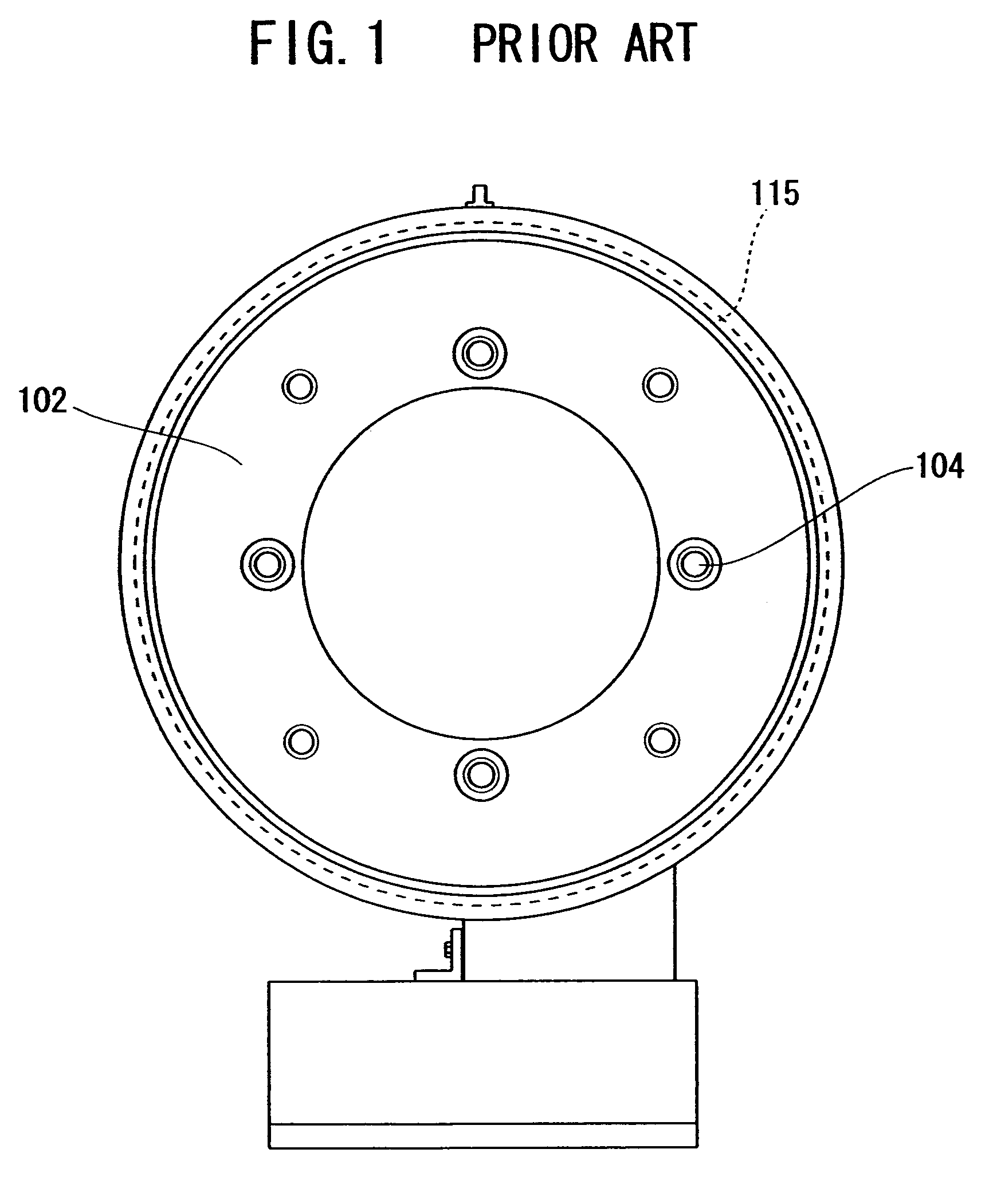
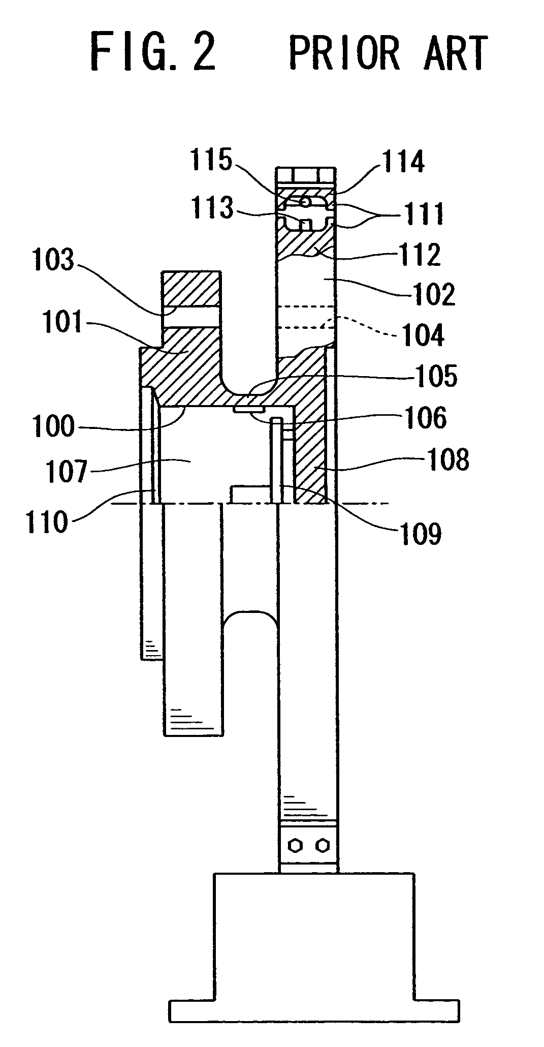
[0034]A preferred embodiment of the present invention will hereinafter be described with reference to FIGS. 4 to 6. The appearance and basic structure of a torque measuring device for a rotating body according to the present invention are the same as those of a conventional torque measuring device for a rotating body as shown in FIGS. 1 to 3, and the description will be made with reference to FIGS. 1 and 3 as well.

[0035]The torque measuring device for a rotating body according to the present embodiment includes a rotary section which is composed of a driving side flange 101 fixedly jointed to a rotating body, a driven side flange 102, and a hollow circular cylinder 100 blinded at one end, defining predetermined outer and inner diameters thus a predetermined wall thickness, and having the driving side and driven side flanges 101 and 102 integrally formed at both end portions thereof.

[0036]The driving side flange 101 has its outer side jointed to a joint member at a driving side in a ...


PUM

PropertyMeasurementUnit
frequencyaaaaaaaaaa
torqueaaaaaaaaaa
magneticaaaaaaaaaa

Abstract

A torque measuring device for a rotating body is provided, which includes: a stationary section; a rotary section; a rotary transformer composed of a primary coil disposed at the stationary section, and a secondary coil disposed at the rotary section, wherein an electric power is transmitted from the stationary section to the rotary section by electromagnetic induction, a torque generated at a rotating body is detected at the rotary section by means of the electric power transmitted, and wherein a detection result is transmitted from the rotary section to the stationary section. In the torque measuring device, a capacitor is connected at the side of the secondary coil of the rotary transformer, and a series resonant circuit is formed by the capacitor in combination with a leakage inductance of the rotary transformer.

Description

[0001]This application claims priority from Japanese Application No. 2004-152769, filed May 24, 2004 (incorporated by reference herein).BACKGROUND OF THE INVENTION[0002]1. Field of the Invention[0003]The present invention relates to a torque measuring device for a rotating body to measure a torque of a rotating body, and more particularly to a torque measuring device for a rotating body, in which a torque amount of a rotating body is detected at a rotary section as an electricity amount that is then transmitted from the rotary section to a stationary section in a non-contact manner.[0004]2. Description of the Related Art[0005]Conventionally, a torque of a rotating body is measured by a device, in which an amount of torsion generated at a hollow circular cylindrical member constituting a rotary section, disposed between a driving shaft rotating and a driven shaft loaded, and fixedly jointed to both the shafts is detected as an electricity amount by strain gauges adhesively attached t...

Claims


Application Information

Patent Timeline
Patent Type & Authority Patents(United States)
IPC IPC(8): E21B7/04G01L3/10G01L3/14G01L3/00G08C17/04G08C19/00G08C23/04
CPCG01L3/1457G01L3/1471
Inventor SUZUKI, SHINYAADACHI, SHIGEYUKI
Owner MINEBEAMITSUMI INC
Why Eureka
Try Eureka