Mat for die cutter

a technology for die cutters and mats, which is applied in the direction of metal working devices, etc., can solve the problems of unsuitable for small tasks, high operating costs, and high equipment costs of rotary die cutting machines

Inactive Publication Date: 2007-09-18
MCGEE SEAN
View PDF8 Cites 0 Cited by
  • Summary
  • Abstract
  • Description
  • Claims
  • Application Information

AI Technical Summary

Benefits of technology

[0015]It is therefore a general object of the present inven...

Problems solved by technology

Rotary die cutting machines are typically expensive pieces of equipment, and are also expensive to operate, and are therefore unsuitable for smaller tasks.
While this is not difficult to accomplish, it is undesirable to find that the apparatus was not operated a sufficient number of times to produce a clean cut.
This can become frustrating if it occurs more than once during a session.
In addition to the frustration of a partially ...

Method used


Image

  • Mat for die cutter
  • Mat for die cutter
  • Mat for die cutter

Examples


Embodiment Construction

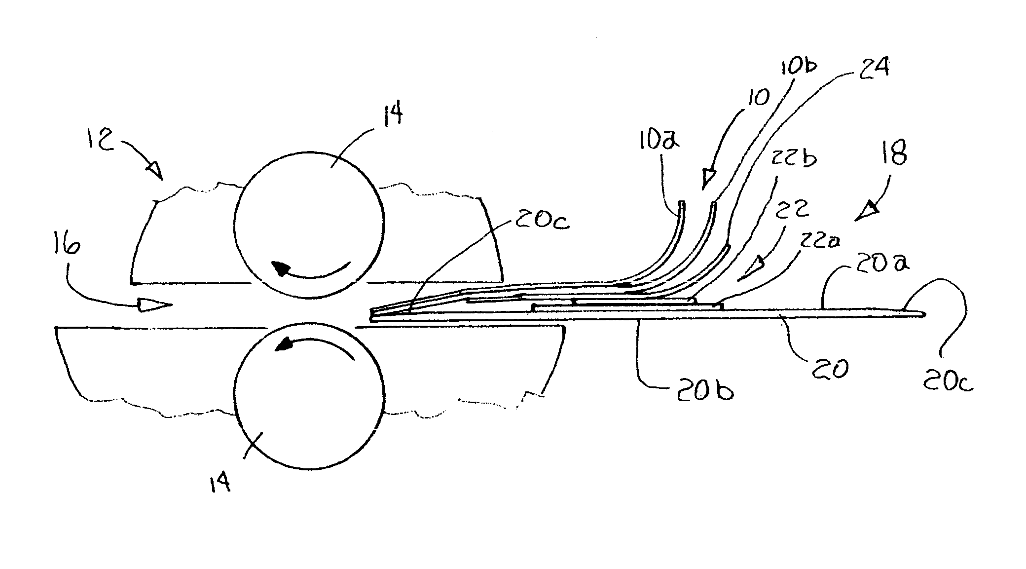
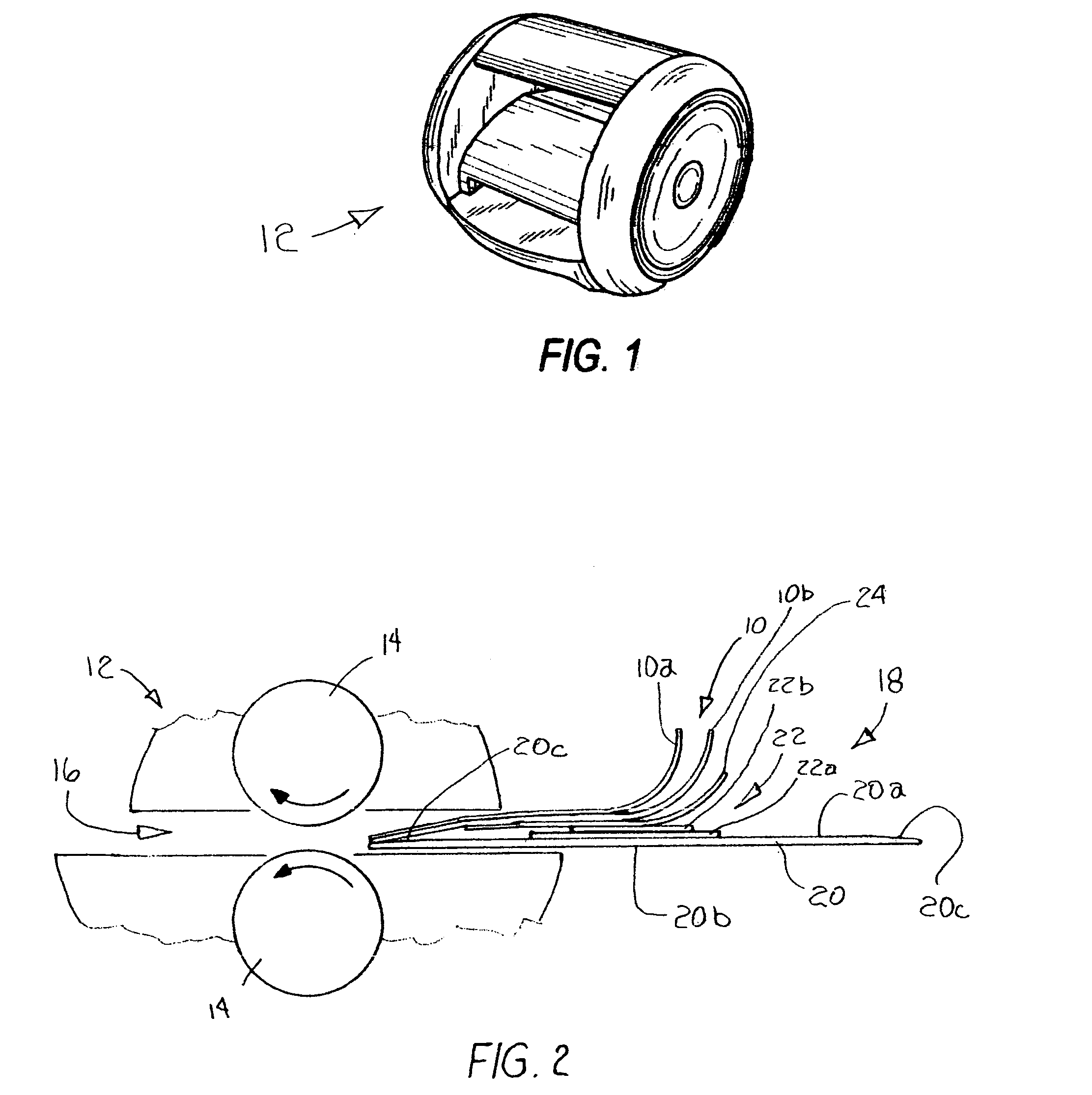
[0025]Referring now to the drawings, and more particularly to FIG. 1, a portable die cutter 12 is shown. While there are several varieties of portable die cutters available on the market, the cutting mat 10 of the present invention is designed specifically for use with a die cutter 12 of the type having opposing rotatable rollers 14, as shown in FIG. 2.

[0026]Die cutter 12 includes a horizontally disposed slot 16 formed therethrough, through which die assembly 18 is directed. Die assembly 18 is drawn between rollers 14 to squeeze the die assembly 18 and cause a die to cut a pattern in a piece of stock material, as described in more detail hereinbelow. Die assembly 18 includes an elongated, planar platform 20 of substantially rigid material, such as a high-density plastic. Platform 20 has a flat upper and lower surfaces 20a and 20b, respectively. However, the upper surface 20a is preferably tapered down to a smaller thickness 20c at each end of the platform. These tapered ends 20c ass...


PUM

PropertyMeasurementUnit
Lengthaaaaaaaaaa
Flexibilityaaaaaaaaaa
Widthaaaaaaaaaa

Abstract

A cutting mat includes a flat, planar sheet of rigid but flexible material with a plastic film affixed to the lower surface and extending across the length and width of the sheet. In the preferred embodiment, the mat is formed of spring steel. A holder for the mat is formed of a planar sheet of plastic material with flaps formed in the holder to removably retain the cutting mat in position on the holder.

Description

CROSS-REFERENCES TO RELATED APPLICATIONS[0001](Not applicable)STATEMENT AS TO RIGHTS TO INVENTIONS MADE UNDER FEDERALLY SPONSORED RESEARCH AND DEVELOPMENT[0002](Not Applicable)INCORPORATION-BY-REFERENCE OF MATERIAL Submitted on a Compact Disc[0003](Not applicable)BACKGROUND OF THE INVENTION[0004](1) Field of the Invention[0005]The present invention relates generally to portable die cutting apparatus, and more particularly to an improved cutting mat for die cutters.[0006](2) Description of Related Art including information disclosed under 37 CFR 1.97, 1.98[0007]Die cutting apparatus have long been used for cutting shapes and patterns from continuous sheet stock material. Rotary die cutting machines are typically expensive pieces of equipment, and are also expensive to operate, and are therefore unsuitable for smaller tasks.[0008]In order to fulfill a need by educational institutions and the home consumer, a variety of smaller, portable roller die cutting machines have been developed....

Claims


Application Information

Patent Timeline
IPC IPC(8): B26D5/08B26D7/00
CPCB26D7/20B26F1/40B26F1/42Y10T83/04Y10T83/8752
Inventor MCGEE, SEAN
Owner MCGEE SEAN
Why Eureka
Try Eureka