Ophthalmic photographic apparatus

a technology of ophthalmic photography and photographic equipment, which is applied in the field of ophthalmic photography equipment, can solve the problems of having to change the setting of each setting, and it is difficult to simultaneously acquire dynamic and still infrared light-excited fluorescence images, and achieves good-quality still images and simple operation.

Inactive Publication Date: 2007-09-18
KOWA CO LTD
View PDF3 Cites 6 Cited by
  • Summary
  • Abstract
  • Description
  • Claims
  • Application Information

AI Technical Summary

Benefits of technology

[0010]According to the invention, the still images can be captured with a flash in the first mode in which the strobe light source is activated and without a flash in the second mode in which it is not activated, making it possible to record still images while dynamic images are being recorded.
[0011]According to the invention, photographic means for still image applications are provided, additionally to photographic means for dynamic and still image applications. When the additional photographic means is selected, the infrared light-excited fluorescence image therefrom is captured with a flash. In such an arrangement, it is possible to capture good-quality still images by infrared light-excited fluorescence with a simple operation.

Problems solved by technology

However, a problem with using a fundus camera for the various photographic modes such as mydriatic photography, non-mydriatic photography, photography by visible light-excited fluorescence and photography by infrared light-excited fluorescence is that a separate camera is required for observation during non-mydriatic photography, for observation and photography of dynamic images during infrared light-excited fluorescence, and for photography of still images by infrared light-excited fluorescence.
Another problem is that it is difficult to simultaneously acquire dynamic and still infrared light-excited fluorescence images, while a further problem is that each setting has to be changed each time there is a change in photographic modes.

Method used


Image

  • Ophthalmic photographic apparatus
  • Ophthalmic photographic apparatus
  • Ophthalmic photographic apparatus

Examples


Embodiment Construction

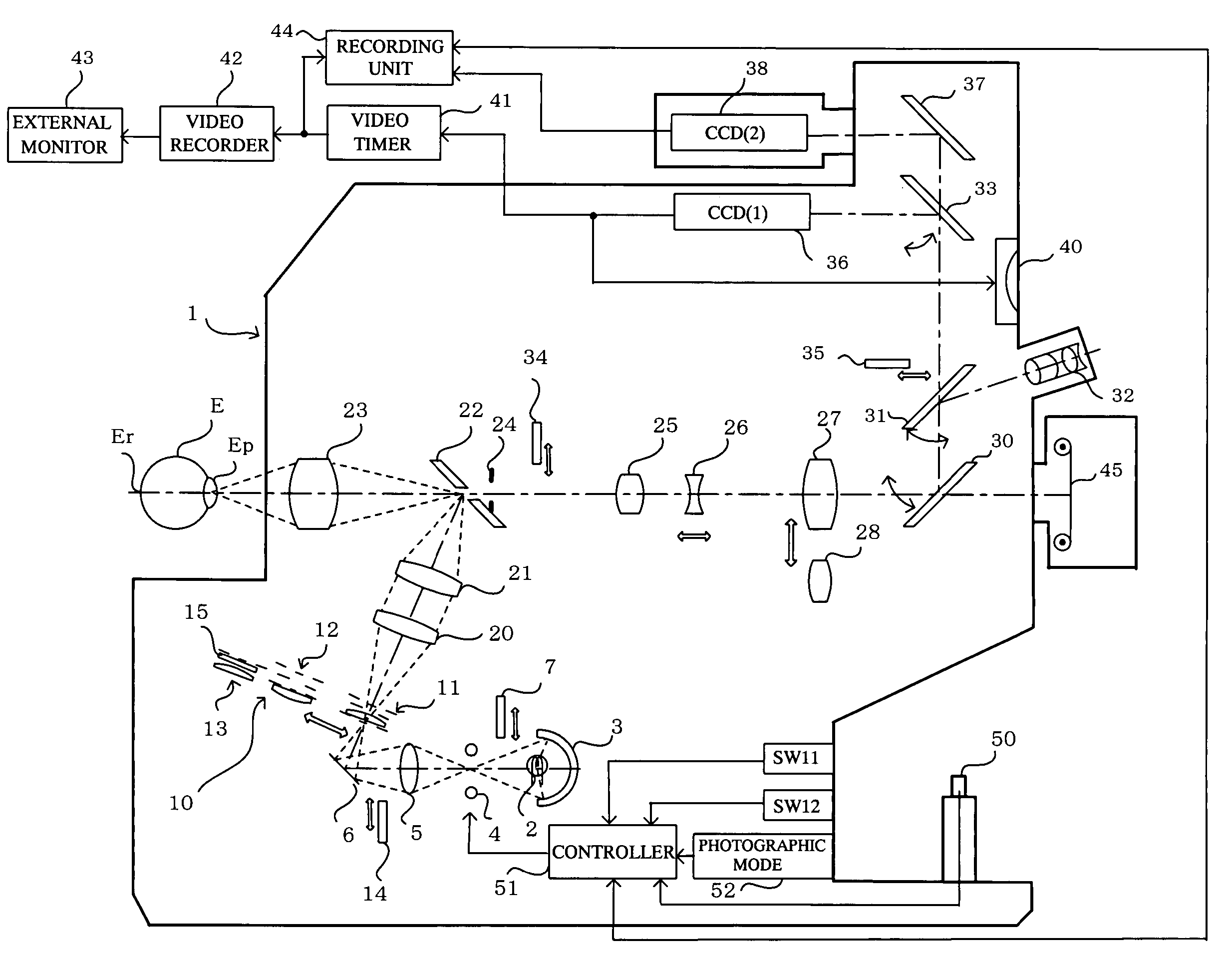
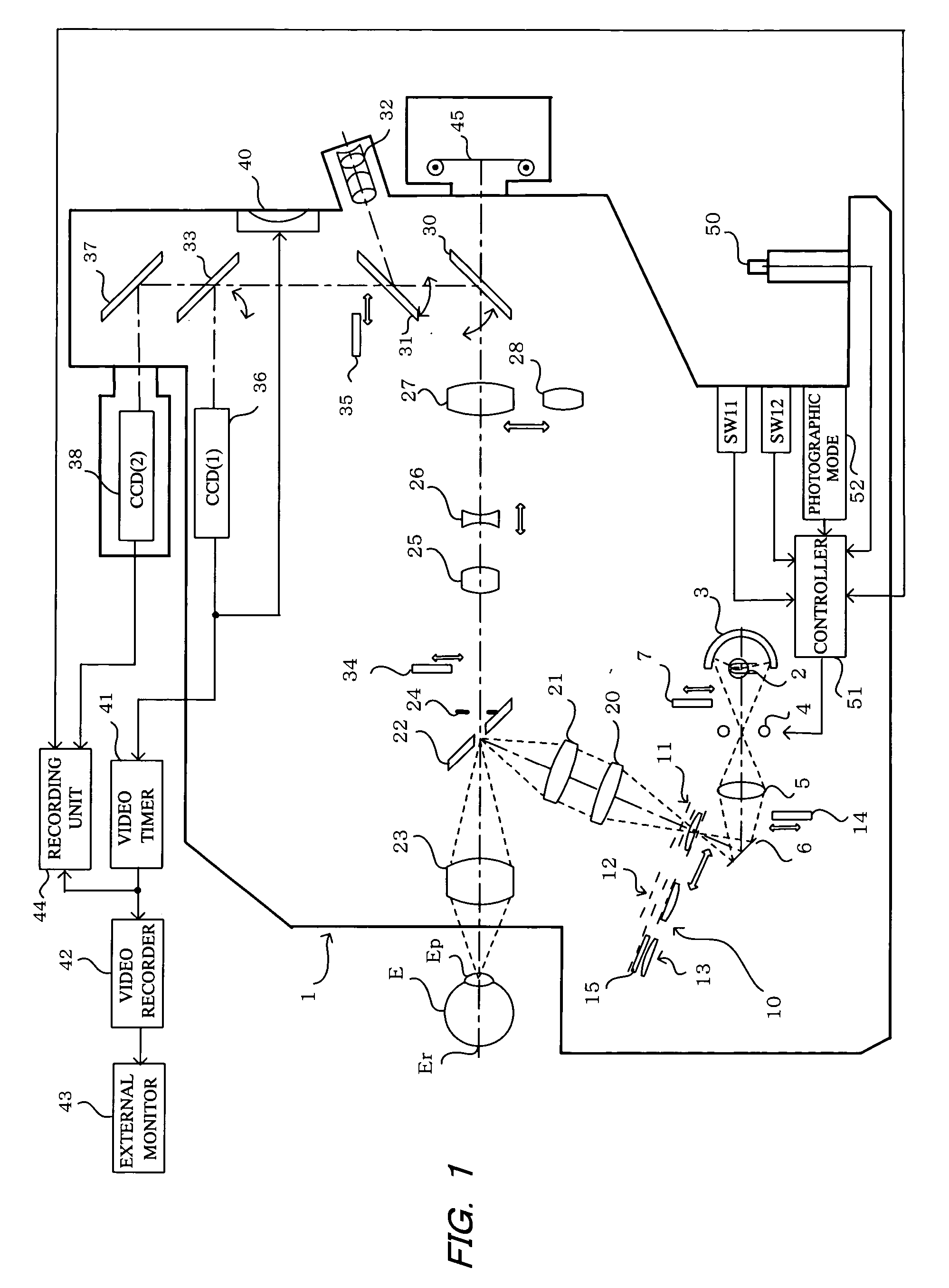
[0018]The embodiments of the invention will now be described with reference to the drawings, starting with FIG. 1 which shows a fundus camera 1 constituting an embodiment of the ophthalmic photographic apparatus of the present invention.

[0019]With reference to FIG. 1, a beam of light from an observation light source 2, such as a halogen lamp or the like, is concentrated by a concave mirror 3, passes through a strobe light source 4 serving as a photographic light source, and a condenser lens 5, and is reflected by a mirror 6 through relay lenses 20 and 21, and reflected by an apertured total-reflection mirror 22, and by means of an objective lens 23, the beam thus reflected by the total-reflection mirror 22 is concentrated at the pupil Ep of an eye E to be examined, and falls incident on the eye fundus Er.

[0020]During non-mydriatic photography, a filter 7 that transmits infrared light and cuts visible light is inserted into the fundus illumination optical path on the downstream side ...


PUM


Abstract

An ophthalmic photographic apparatus is provided that is readily able to capture dynamic and still eye fundus images by infrared light-excited fluorescence. A CCD device that is sensitive to infrared light is used to capture images of the eye fundus as dynamic and still images. When the shutter button is pressed, infrared light-excited fluorescence images are obtained as still images and stored in a recording unit. The infrared light-excited fluorescence image of the eye fundus is captured as a still image with or without a flash from a strobe light source. Such an arrangement makes it possible to capture still images even when dynamic images are being recorded.

Description

BACKGROUND OF THE INVENTION[0001]1. Field of the Invention[0002]The present invention relates to an ophthalmic photographic apparatus, and more particularly to an ophthalmic photographic apparatus such as a fundus camera or the like that can be used for non-mydriatic and mydriatic color photography, for photography by visible light-excited fluorescence and for photography by infrared light-excited fluorescence.[0003]2. Description of the Prior Art[0004]There are ophthalmic photographic apparatuses such as fundus cameras and the like that in addition to being capable of photographing non-mydriatic or mydriatic color images of the eye fundus, are also capable of photographing eye fundus images by visible light-excited fluorescence (also designated as fluorescein angiography; FAG) or by infrared light-excited fluorescence (also designated as indocyanine green angiography; ICG). For each such photographic mode, a camera is provided having characteristics suitable for observation and for...

Claims


Application Information

Patent Timeline
Patent Type & Authority Patents(United States)
IPC IPC(8): A61B3/14
CPCA61B3/14
Inventor MATSUMURA, KAZUNORIMIZUOCHI, MASAHARU
Owner KOWA CO LTD
Why Eureka
Try Eureka