X-ray CT apparatus with a filtering element exhibiting a maximum absorption at its center

a filter element and ct technology, applied in the field of x-ray computed tomography, can solve the problems of deteriorating image quality and often unadvisable rotation of animals, and achieve the effects of good radiation dose reduction, high image quality in practice, and convenient manufacturing

Active Publication Date: 2016-03-17
BRUKER MICROCT NV
View PDF9 Cites 2 Cited by
  • Summary
  • Abstract
  • Description
  • Claims
  • Application Information

AI Technical Summary

Benefits of technology

[0028]In a further development of this embodiment, the filter element exhibits a thickness variation along the cross direction (y) by a factor of 2 or more, preferably by a factor of 5 or more, in the area of the filter element which shadows the detection area of the 2D x-ray detector. Such a variation can easily be manufactured and establishes an intensity variation of the transmitted high energy X-rays at the projection images which can well be compensated for under typical measurement conditions. Note that thickness variation typically does not exceed a factor of 20, though.
[0029]In an advantageous embodiment, the spatially varying X-ray absorption capability exhibits an absorption variation along the cross direction (y) by a factor of 5 or more, preferably by a factor of 20 or more, most preferably by a factor of 50 or more, in the area of the filter element which shadows the detection area of the 2D X-ray detector. The factors apply at least to X-rays of 5 keV (and preferably to all low energy X-rays of about 1 keV-10 keV), and possibly also to high energy X-rays (with an X-ray energy of about 10 keV-100 keV); however note that the absolute absorption is typically much less for high energy X-rays than for low energy X-rays. The factors compare the strongest filtered X-ray intensity with the weakest filtered X-ray intensity behind the filter element (assuming a uniform illumination of the filter element). This embodiment has shown good radiation dose reduction and still high image quality in practice. An intensity factor of about 50 (and often more) for the projection images can, under typical measurement conditions, still be compensated for by back projection when calculating cross-sections.
[0030]Also preferred is a an embodiment wherein the X-ray absorption capability exhibits a monotonic decreasing absorption, in particular strict monotonic decreasing absorption, on both sides away from the zero position (y0) along the cross direction (y), in the area of the filter element which shadows the detection area of the 2D X-ray detector. With increasing distance from the rotation axis, the information from the entirety of the projection images becomes less, and therefore less absorption of the filter element can be compensated for. With this embodiment, gradually more X-ray intensity is provided at the object when departing from the rotation axis, so uniform cross-section image quality may be obtained in summary. With a strict monotonic decreasing absorption, sharp changes in the absorption capability of the filter element are excluded, so artefacts in image reconstruction are avoided. Note that this embodiment is typically realized by a thickness variation of the filter element exhibiting a monotonic decreasing thickness, in particular strict monotonic decreasing thickness, on both sides away from the zero position (y0) along the cross direction (y), in the area of the filter element which shadows the detection area of the 2D X-ray detector.

Problems solved by technology

When dealing with live animals, rotating the animal is often not advisable.
However, if the X-ray intensity becomes too low, or the X-ray energy becomes too high, the image quality will deteriorate.

Method used


Image

  • X-ray CT apparatus with a filtering element exhibiting a maximum absorption at its center
  • X-ray CT apparatus with a filtering element exhibiting a maximum absorption at its center
  • X-ray CT apparatus with a filtering element exhibiting a maximum absorption at its center

Examples


Embodiment Construction

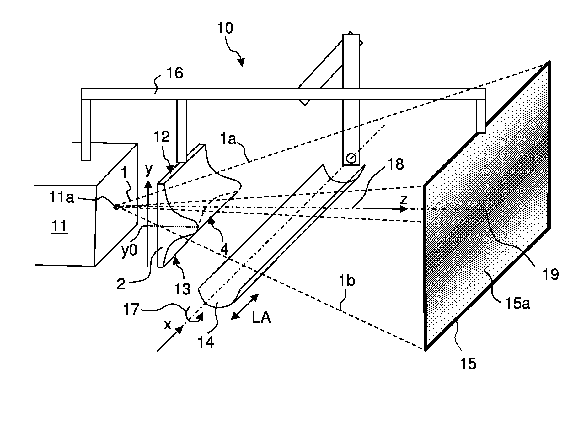
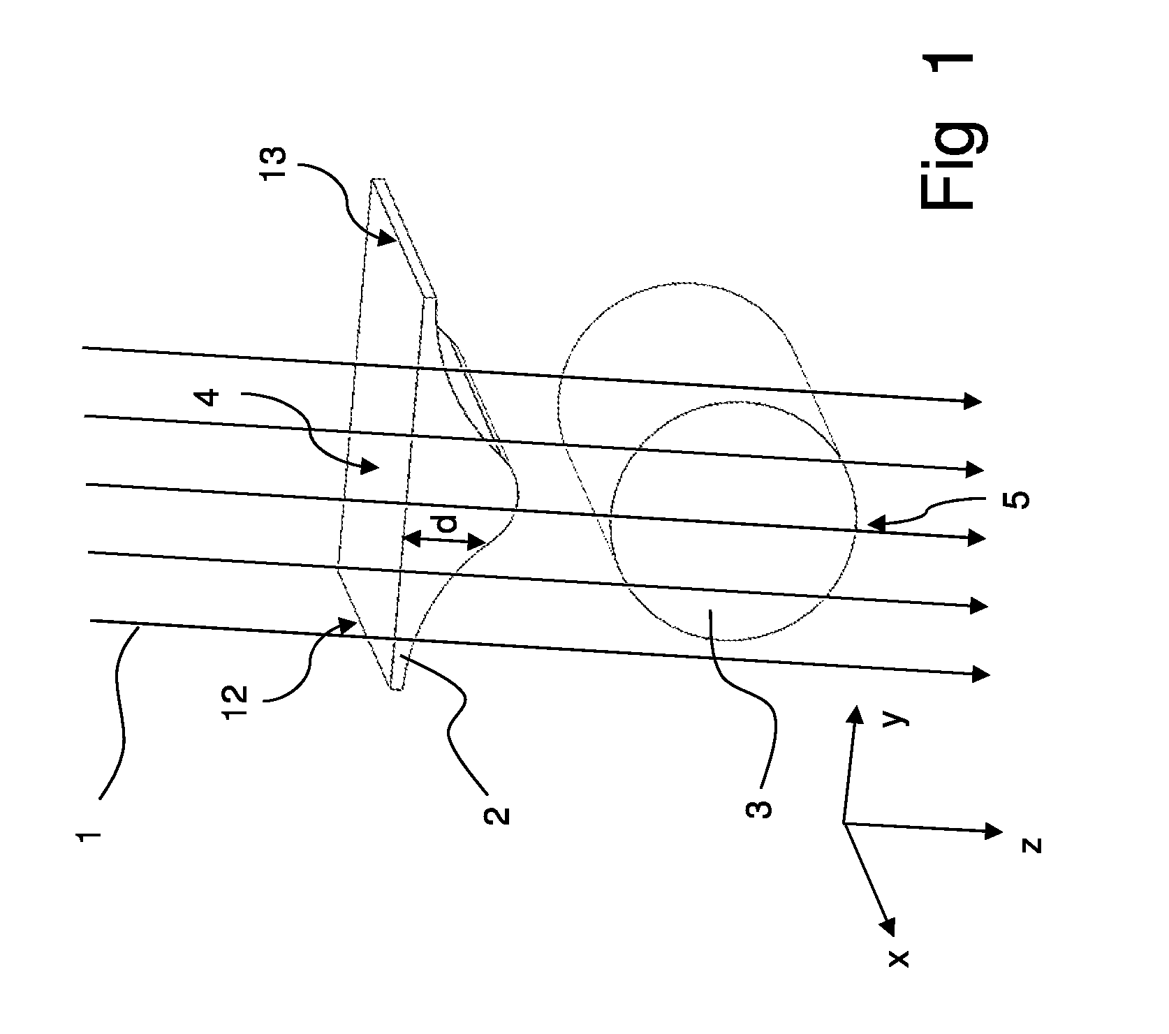
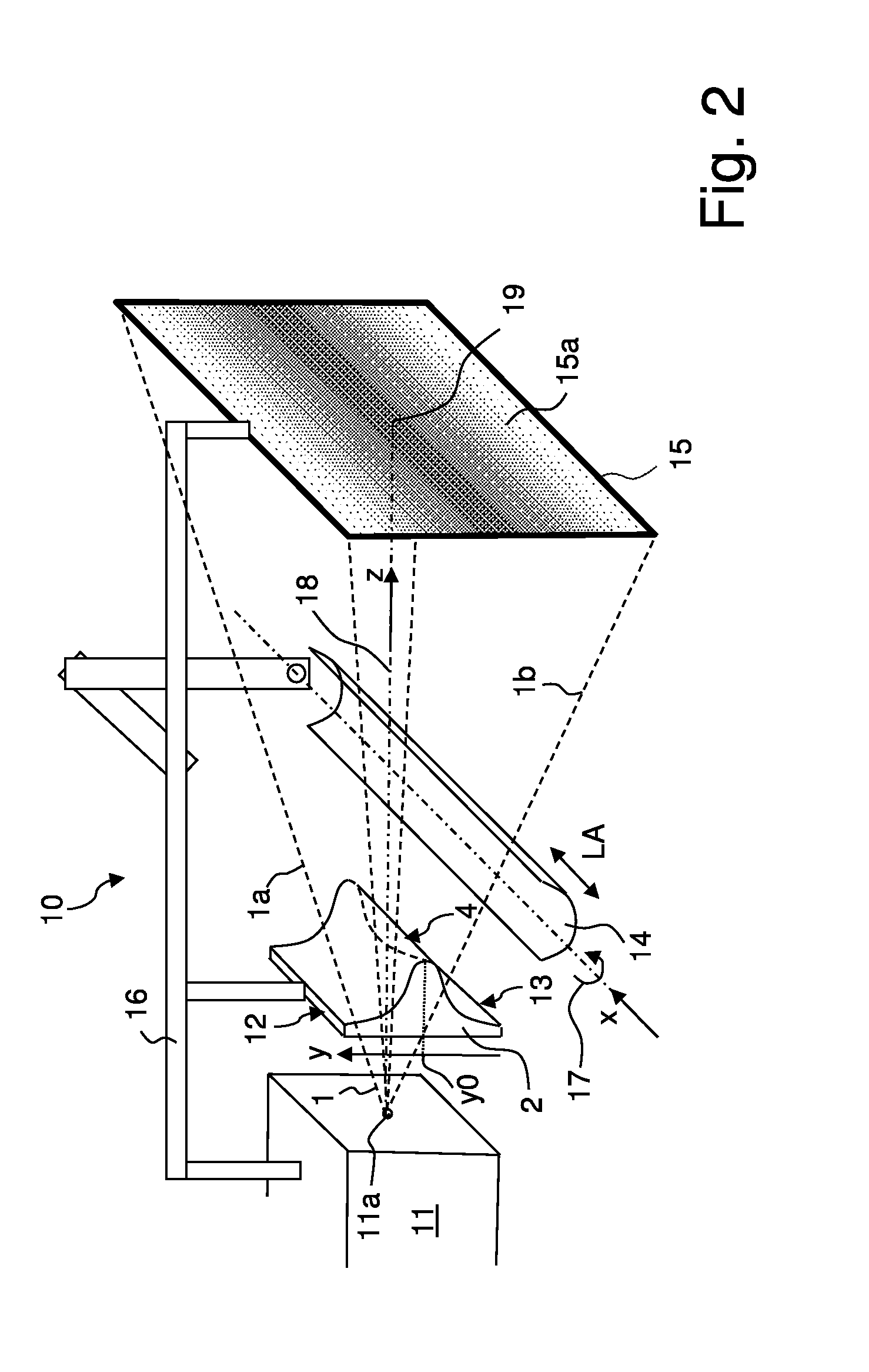
[0042]In X-ray computed tomography, a large number of X-ray images (projection images) are recorded, with each recording coming along with an exposure of the object to be investigated with X-rays. X-rays may damage the material exposed, in particular by ionization. In human or animal tissue, X-rays may in particular induce carcinogenesis. The present invention therefore seeks to reduce the radiation dose to objects investigated in X-ray computed tomography.

[0043]The absorbed dose depends on absorbing coefficients of materials in the object, thickness of the object materials, and the intensity and energy distribution in the primary beam. The first two factors cannot be changed by the scanning setup, but the energy spectrum and intensity distribution in the primary beam can be adjusted in such a way that the absorbed dose will be reduced without significant impact to the quality of results of tomographical reconstruction, in accordance with the invention.

[0044]The central, in general ...


PUM


Abstract

An X-ray computed tomography (=CT) apparatus (10) has a filter element (2) for attenuating an X-ray beam (1). The filter element (2) has a spatially varying X-ray absorption capability along a cross direction (y) which is perpendicular to both the beam axis (z) of the X-ray beam and to a rotation axis (x) of a gantry. The spatially varying X-ray absorption capability exhibits a maximum absorption along the cross direction (y) at a zero position (y0), wherein X-rays passing through the filter element (2) at the zero position (y0) intersect the rotation axis (x). The CT apparatus allows for further reduction of the radiation dose for an object to be investigated, while simultaneously retaining high image quality.

Description

[0001]This application claims Paris convention priority from EP 14 185 226.9 filed Sep. 17, 2014 the entire disclosure of which is hereby incorporated by reference.BACKGROUND OF THE INVENTION[0002]The invention relates to an X-ray computed tomography (=CT) apparatus, comprising[0003]an X-ray source for emitting an X-ray beam, in particular a divergent X-ray beam, along a beam axis (z),[0004]a filter element for attenuating the X-ray beam,[0005]a stage for an object to be investigated with the attenuated X-ray beam,[0006]a 2D X-ray detector with a detection area,[0007]and a gantry system capable of rotating either the entirety of the X-ray source, the filter element and the 2D X-ray detector, or the stage for the object with respect to a rotation axis (x) which is perpendicular to the beam axis (z), wherein the filter element has a spatially varying X-ray absorption capability along a cross direction (y) which is perpendicular to both the beam axis (z) and the rotation axis (x).[0008...

Claims


Application Information

Patent Timeline
Patent Type & Authority Applications(United States)
IPC IPC(8): A61B6/00
CPCA61B6/508A61B6/4035G21K1/10
Inventor SASOV, ALEXANDERHOSTENS, JEROEN
Owner BRUKER MICROCT NV
Why Eureka
Try Eureka