System and method for monitoring status of a visual signal device

a visual signal and status monitoring technology, applied in the field of system and method for detecting and reporting railroad signal light status, can solve the problems of laborious methods, inability to provide an insight as to the condition of the entire optical system of the signal unit, and inability to provide a reliable, long-term, unambiguous indication of lamp performan

Active Publication Date: 2007-09-18
GENERAL ELECTRIC CO
View PDF9 Cites 10 Cited by
  • Summary
  • Abstract
  • Description
  • Claims
  • Application Information

AI Technical Summary

Problems solved by technology

Such methods do not provide insight as to the condition of the entire optical system of the signal unit (i.e. lens, reflectors).
These methods are generally labor intensive to install and to calibrate and do not provide a reliable, unambiguous, long-term indication of lamp performance.

Method used


Image

  • System and method for monitoring status of a visual signal device
  • System and method for monitoring status of a visual signal device
  • System and method for monitoring status of a visual signal device

Examples


third embodiment

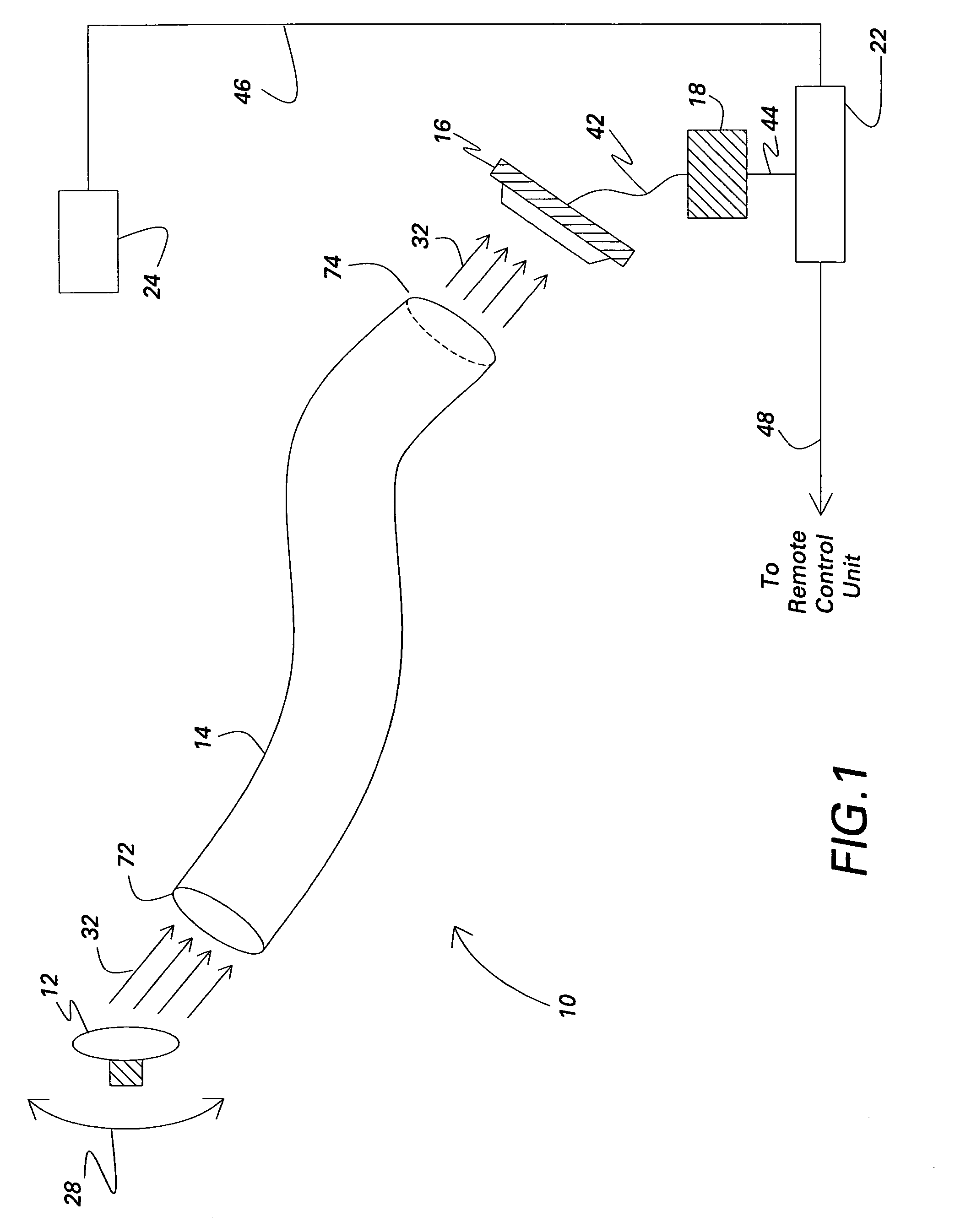
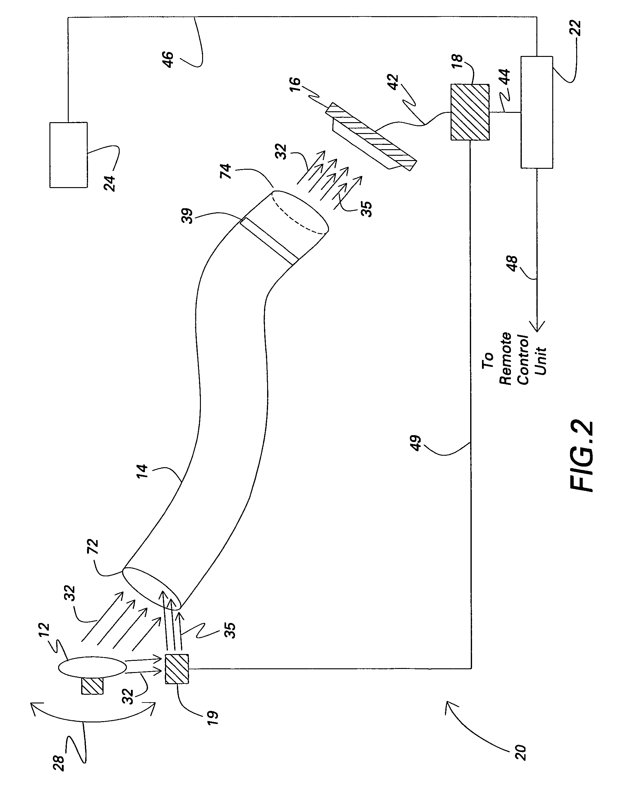
[0022]FIG. 2 is a simplified schematic diagram of an exemplary system 20 for monitoring status of visual signal lamp 12 in accordance with the invention. The system 20 is enhanced by the addition of a lamp-head voltage detection circuitry 19, an electrical conductor 49 that connects the lamp-head voltage detection circuitry 19 with the threshold detection circuitry 18 and a light frequency filter 39. Other than the lamp-head voltage detection circuitry 19, the conductor 49 and the light frequency filter 39, the system 20 is substantially similar to system 10 shown in FIG. 1. Components in system 20 that are identical to components of system 10 are identified in FIG. 2 using the same reference numerals used in FIG. 1.

[0023]Referring to FIG. 2, the lamp-head voltage detection circuitry 19 is located at the lamp-head (not shown) to measure the voltage directly. Positioning the lamp-head voltage detection circuitry 19 can be embodied in different ways. In one embodiment of the invention...

fourth embodiment

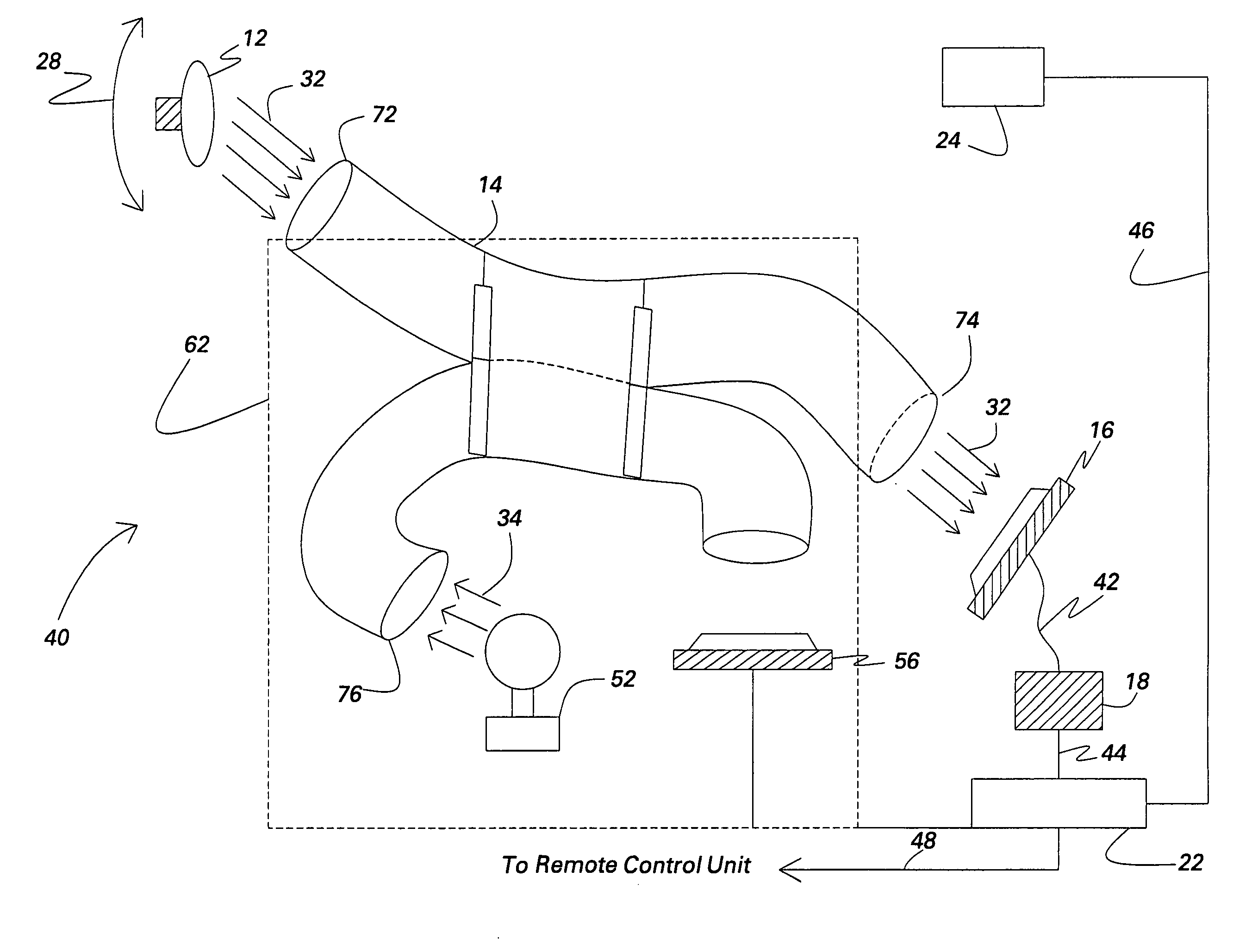
[0031]FIG. 4 is a simplified schematic diagram of an exemplary system 40 for monitoring status of visual signal lamp 12 in accordance with the invention. The system 40 is enhanced by the addition of a continuity checking circuitry 62 to check the continuity of the optical fiber 14. The continuity checking circuitry 62 includes a test optical light source 52, a test photodetector 56, a test optical fiber 54 and two fiber optic splitters 64 and 66. Other than the test optical light source 52, the test photodetector 56, the test optical fiber 54 and the two fiber optic splitters 64 and 66, system 40 is substantially similar to system 10 shown in FIG. 1. Components in system 40 that are identical to components of system 10 are identified in FIG. 4 using the same reference numerals used in FIG. 1.

[0032]The continuity checking circuitry 62 is used for checking the continuity of optical fiber 14 used to monitor the status of one or more signal lamps 12. The continuity checking circuitry 62...


PUM


Abstract

System and method for monitoring status of a visual signal lamp. The system includes at least one optical fiber comprising a first end and a second end. The first end is positioned proximate to the signal lamp and is oriented to capture a portion of light signal emitted by the signal lamp when the signal lamp is illuminated. The system also includes a photodetector positioned proximate to the second end of the optical fiber and configured to receive the portion of light signal. The system further includes a threshold detection circuitry connected to the photodetector and configured to detect a lighting parameter in relation to the signal lamp according to a predetermined criterion.

Description

BACKGROUND[0001]This invention relates generally to a system and method for detection of signal light parameters, and more particularly to a system and method for detecting and reporting railroad signal light status.[0002]Visual railway signals, particularly signal lamps, are important components of a modern railway system and its operation. It is desirable to be able to verify that a signal lamp is in its desired state, illuminated, dark, or flashing, i.e., periodically cycling between illuminated and dark states. It is also desirable to detect and quantify the optical power exiting the signal head. Such optical power can be reduced by several factors including bulb age, dirt on lens or reflector surfaces, and damage to lens. Previous methods monitor the current drawn by a signal lamp to detect loss of filament. Such methods do not provide insight as to the condition of the entire optical system of the signal unit (i.e. lens, reflectors). Newer methods of monitoring flashing warnin...

Claims


Application Information

Patent Timeline
Patent Type & Authority Patents(United States)
IPC IPC(8): F21V23/00B60Q11/00
CPCB61L5/1881B61L2207/02H05B45/58
Inventor DAVENPORT, DAVID MICHAELHERSHEY, JOHN ERIKTOLLIVER, TODD RYAN
Owner GENERAL ELECTRIC CO
Why Eureka
Try Eureka