Flexible interconnect cable with insulated shield and method of manufacturing

a technology of interconnection cable and shield, which is applied in the direction of insulated conductor, cable, coupling device connection, etc., can solve the problems of exposing the signal conductor to shorting with the braid or to each other, affecting the performance of the signal wire, so as to limit electrical noise and interference and prevent radio interferen

Inactive Publication Date: 2007-09-18
PRECISION INTERCONNECT
View PDF10 Cites 18 Cited by
  • Summary
  • Abstract
  • Description
  • Claims
  • Application Information

AI Technical Summary

Benefits of technology

[0002]Certain demanding applications require miniaturized multi-wire cable assemblies. To avoid undesirably bulky cables when substantial numbers of conductors are required, very fine conductors are used. To limit electrical noise and interference, coaxial wires having shielding are used for the conductors. In other application, twisted pairs, parallel pairs, unshielded insulated single wires, and other configurations may be employed. A bundle of such wires is surrounded by a conductive shield formed of braided small wires to prevent radio interference from being emitted or received by the cable components. An outer protective sheath covers the shield.
[0004]Because the stresses and wear are generally concentrated at the ends of a cable near strain relief elements such as disclosed in U.S. Pat. No. 6,672,894 (incorporated herein by reference), measures have been taken to protect the cable bundle at such stress points. As disclosed in U.S. Pat. No. 6,580,034 (incorporated herein by reference), the cable bundle may be wrapped at its ends near the stress points with a low-friction Teflon tape. While effective, this reduces the benefits of a loose shield, which provides the desired supple effect. Tape-wrapped wires are captured in a bundle that does not readily flatten to permit easy bending to small radiuses. This is not problematic for many applications, because the flexibility remains excellent over nearly the entire length of the cable. However, in some applications, flexibility near the ends is a valued characteristic that is preferably not sacrificed. Moreover, for applications in which there is a risk of damage due to intense stresses causing wear anywhere along the entire cable length, wrapping the entire cable bundle with tape to prevent such wear unacceptably sacrifices the flexibility desired for many applications.

Problems solved by technology

Because the braid is formed of bare metal wires, it may have an abrasive effect on the bundle of signal wires in certain applications where flexing and external stresses are extreme.
Such abrasion may generate open failures in the individual shield wires of coaxial wire components, generating signal noise during operation due to shorting between the now-open wire shield and the outer braided cable shield.
Other failure modes include abrasion of wire insulation, which may expose the signal conductors to shorting with the braid or to each other.
While effective, this reduces the benefits of a loose shield, which provides the desired supple effect.
Tape-wrapped wires are captured in a bundle that does not readily flatten to permit easy bending to small radiuses.
Moreover, for applications in which there is a risk of damage due to intense stresses causing wear anywhere along the entire cable length, wrapping the entire cable bundle with tape to prevent such wear unacceptably sacrifices the flexibility desired for many applications.

Method used


Image

  • Flexible interconnect cable with insulated shield and method of manufacturing
  • Flexible interconnect cable with insulated shield and method of manufacturing
  • Flexible interconnect cable with insulated shield and method of manufacturing

Examples


Embodiment Construction

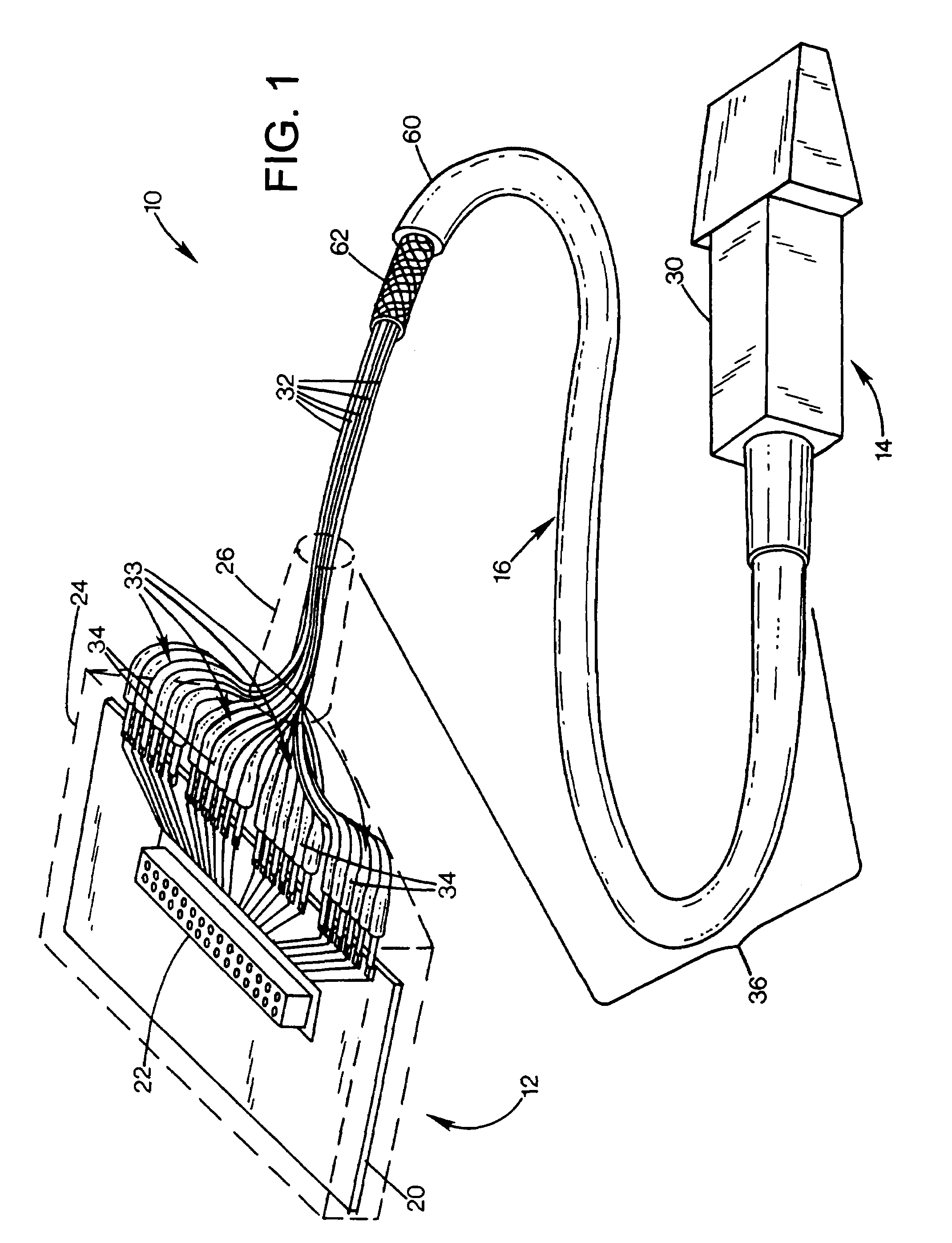
[0015]FIG. 1 shows a cable assembly 10 having a connector end 12, a transducer end 14, and a connecting flexible cable 16. The connector end and transducer ends are shown as examples of components that can be connected to the cable 16. In this example, the connector end includes a circuit board 20 with a connector 22 for connection to an electronic instrument such as an ultrasound imaging machine. The connector end includes a connector housing 24, and strain relief 26 that surrounds the end of the cable. On the opposite end, an ultrasound transducer 30 is connected to the cable.

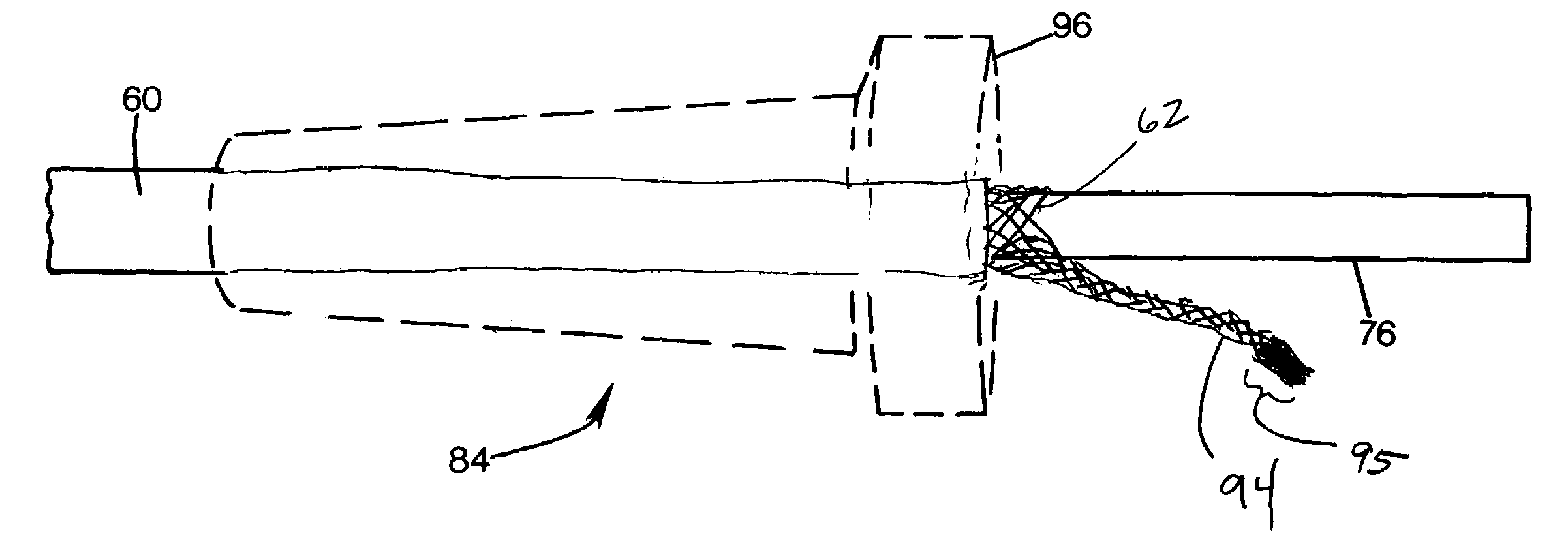
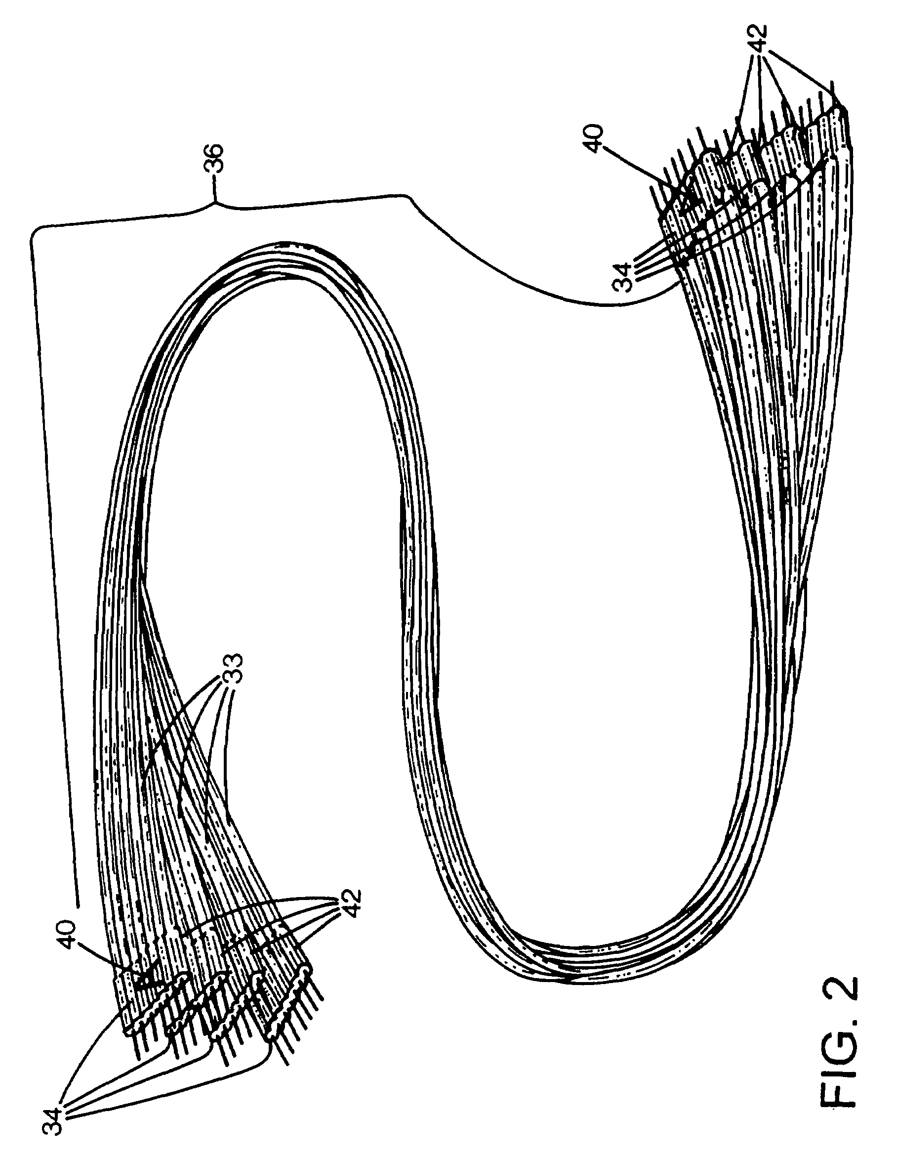
[0016]The cable 16 includes a multitude of fine coaxially shielded wires 32. As also shown in FIG. 2, the wires are arranged into groups 33, with each group having a ribbonized ribbon portion 34 at each end, and an elongated loose portion 36 between the ribbon portions and extending almost the entire length of the cable. Each ribbon portion includes a single layer of wires arranged side-by-side, adhered to ea...


PUM


Abstract

A cable assembly having a plurality of wires, each having a first end and an opposed second end. A sheath including an shield encompasses all the wires. The shield is a braid formed of a plurality of braid wires, and each of the braid wires has an insulating coating. The wires of the braid may be gathered at an end into a pigtail. The insulation is removed from the wires at the pig tail. The insulation may be removed by dipping the pigtail in a high temperature solder bath.

Description

FIELD OF THE INVENTION[0001]This invention relates to multiple wire cables, and more particularly to small gauge coaxial wiring.BACKGROUND AND SUMMARY OF THE INVENTION[0002]Certain demanding applications require miniaturized multi-wire cable assemblies. To avoid undesirably bulky cables when substantial numbers of conductors are required, very fine conductors are used. To limit electrical noise and interference, coaxial wires having shielding are used for the conductors. In other application, twisted pairs, parallel pairs, unshielded insulated single wires, and other configurations may be employed. A bundle of such wires is surrounded by a conductive shield formed of braided small wires to prevent radio interference from being emitted or received by the cable components. An outer protective sheath covers the shield.[0003]Some applications requiring many different conductors prefer that a cable be very flexible, supple, or “floppy.” This has been achieved by providing a shielding bra...

Claims


Application Information

Patent Timeline
Patent Type & Authority Patents(United States)
IPC IPC(8): H01R9/05
CPCH01B7/0892H01R24/562H01B11/00H01R2107/00H01R9/032H01R13/65912H01B11/06
Inventor BUCK, ARTHUR GLENDAUGHERTY, DANA ANNETRAN, THANH HOANGNGO, KRISTIN THU HUONG
Owner PRECISION INTERCONNECT
Why Eureka
Try Eureka