Antenna mounted on vehicle

a technology for antennas and vehicles, applied in the field of antennas, can solve the problems of insufficient reliability of watertight structures, deformation of ring-shaped ridges, and inability to manufacture separate pads b>20/b> for each vehicle body type, and achieve the effect of enhancing the watertightness of the circuit board

Inactive Publication Date: 2007-09-18
YOKOWO CO LTD
View PDF9 Cites 21 Cited by
  • Summary
  • Abstract
  • Description
  • Claims
  • Application Information

AI Technical Summary

Benefits of technology

[0007]It is therefore an object of the invention to provide an antenna that will not generate deformation in the curved surface of a vehicle body on which the antenna is mounted, while achieving reliable waterproofness.
[0016]With this configuration, even when a small amount of rain water enters into the inside from an edge portion of the casing, the wall member prevents the rain water from entering into the housing space, and hence prevents the circuit board from being exposed to the rain water. Therefore, what is necessary to prevent the rain water from entering into the vehicle body through the through hole is to bring the waterproof member surrounding the through hole into firm contact with the vehicle body in a small area. This avoids deformation in the complicated curved surface of the vehicle body.
[0018]In this case, the number of necessary components can be reduced. Further, a pad having one shape can be applied to a larger number of vehicle body types without generating deformation in the curved surface of the vehicle. This permits mass production, and hence is economical.
[0020]In this case, the circuit board is arranged in the housing space and penetrated by the feeding terminal. This achieves reliable electric connection between the feeding terminal and the circuit board. Further, the work of establishing the electric connection between the feeding terminal to the circuit board and the work of arranging the circuit board in the housing space can be performed easily and reliably in a single work step.
[0022]In this case, the waterproofness with respect to the circuit board can be enhanced.

Problems solved by technology

Nevertheless, separate fabrication of the pad 20 for each vehicle body type is not economical.
However, when the pad deforms elastically in correspondence to the curved surface of a vehicle body, the ring-shaped ridge also deforms.
Since a pad is brought into elastic contact with a lower end periphery of the case solely by virtue of the elasticity of a ring-shaped ridge of the pad, the above deformation causes a change in the elasticity for establishing elastic contact with the lower end periphery of the case, and thereby may cause insufficient reliability in the watertight structure.

Method used


Image

  • Antenna mounted on vehicle
  • Antenna mounted on vehicle
  • Antenna mounted on vehicle

Examples


Embodiment Construction

[0035]Embodiments of the invention will be described with reference to the accompanying drawings.

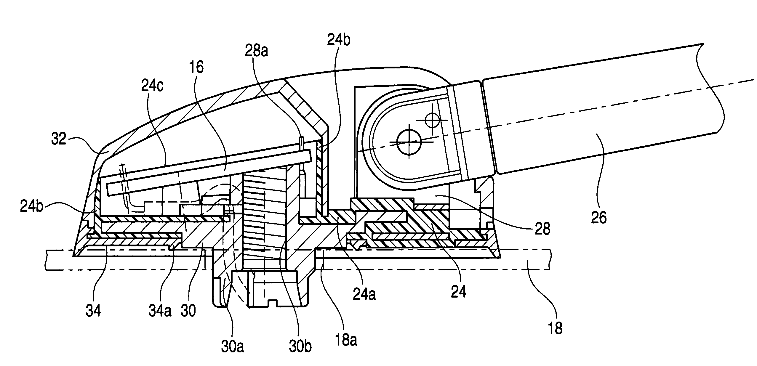
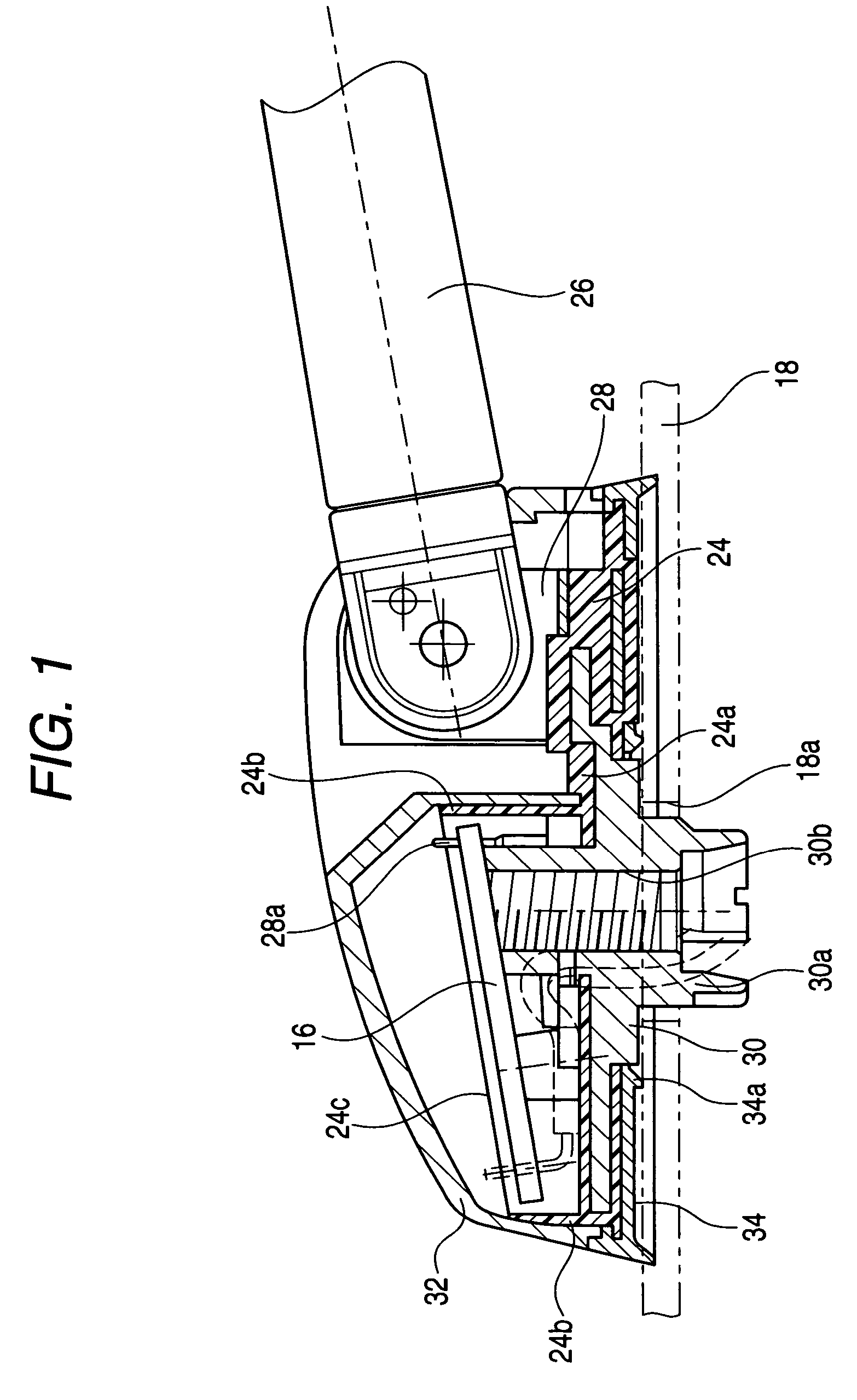
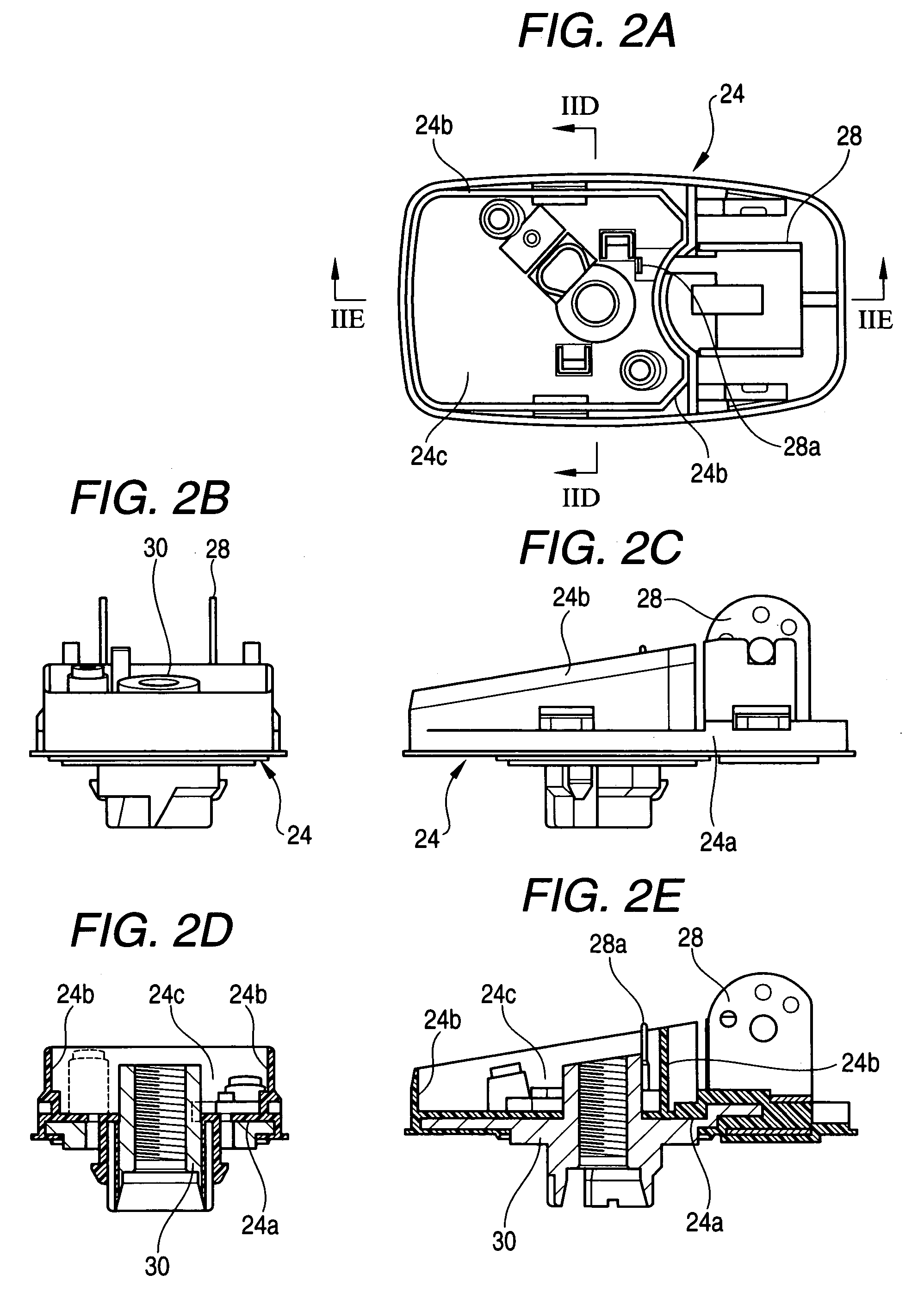
[0036]FIGS. 1 through 4 show an antenna to be mounted on a vehicle body 18, according to one embodiment of the invention. In this antenna, a base member 24 is provided with a metallic base plate 28 for supporting a base end of an antenna section 26 in a pivotable manner, and a metallic base 30 for fixing the base member 24 to a vehicle body 18, where the base plate 28 and the base 30 are formed integrally by resin-molding. In this resin-molded part 24a, a wall 24b is vertically formed by also integral molding to surround the entire periphery of the part 24a, thereby forming a housing section 24c having an opening solely on top.

[0037]Further, a feeding terminal 28a formed integrally with the base plate 28 is arranged in a manner penetrating the wall 24b in a watertight structure and then protruding upward inside the housing section 24c. Then, the housing section 24c in which a circuit boa...


PUM


Abstract

In an antenna adapted to be mounted on a vehicle body, a base member supports a base end of the antenna element. A screw member is extended from the base member and adapted to be inserted into a though hole formed in the vehicle body. A wall member is extended from the base member to define a housing space. A circuit board is disposed in the housing space. A casing covers the housing space such that an inner face thereof comes in contact with an outer face of the wall member. A waterproofing member is disposed between the base member and the vehicle body so as to surround an entire periphery of the through hole.

Description

BACKGROUND OF THE INVENTION[0001]The present invention relates to an antenna which is to be mounted on a vehicle, and which is provided with an improved waterproof structure with respect to a circuit board arranged in a base member of the antenna.[0002]An example of the structure of a related-art antenna will be described below with reference to FIGS. 5 and 6. In an upper part of an approximately hat-shaped case 10, a base end of an antenna section 12 is arranged in a pivotable manner. A base member 14 is fixed to a lower end opening face of the case 10 by a screw or the like. A circuit board 16 and the like are arranged in a space formed by the case 10 and the base member 14. A screw 14a protruding in a bottom surface of the base member 14 is inserted into a hole 18a drilled in the vehicle body 18. A nut which is not shown is engaged from the inside of the vehicle body 18, so that the base member 14 is fixed to the vehicle body 18.[0003]A pad 20 having elasticity is inserted betwee...

Claims


Application Information

Patent Timeline
Patent Type & Authority Patents(United States)
IPC IPC(8): H01Q1/32
CPCH01Q1/3275
Inventor GORAI, TATSUOOHNO, SADAO
Owner YOKOWO CO LTD
Why Eureka
Try Eureka