Sealing gasket for lower tool of a sealing station of a vacuum packaging machine

a vacuum packaging machine and sealing gasket technology, which is applied in the directions of transportation and packaging, packaging, transit packaging, etc., can solve the problems of shortening the life of the sealing gasket, forming defective packages, and causing greater force or load, so as to eliminate the production of defective packages

Active Publication Date: 2007-09-25
EPSTEIN MOSHE
View PDF11 Cites 2 Cited by
  • Summary
  • Abstract
  • Description
  • Claims
  • Application Information

AI Technical Summary

Benefits of technology

[0005]It is, therefore, the primary objective of the present invention to provide an improved sealing gasket for a vacuum-sealing station of a vacuum packaging machine, which substantially eliminates the production of defective packages owing to the unevenness, or non-levelness, of the heating element.
[0006]It is, also, the primary objective of the present invention to provide an improved sealing gasket for a vacuum-sealing station of a vacuum packaging machine, which substantially eliminates the production of defective packages, and which substantially eliminates the need to provide ever-greater loading of the heating tool, over time and use, against the lower tool of the sealing station.

Problems solved by technology

However, there are a number of problems associated with making the sealing gasket of such hard material.
Since the heating elements are not perfectly level, especially over time and use, it is common that some packages are formed that are not adequately sealed by the heating tool because of this unevenness or non-levelness of the heating elements, which not only require that these defective packages be discarded, but also require that time be spent by the operators of the machine in order to check for and discard the defective packages and remove the contents of these defective packages.
While this method produces some benefit, it is only partially successful and requires ever-greater force or load as the heating tool becomes ever-more uneven or non-level, which leads to a shorter life of the heating element and related equipment and the sealing gasket.

Method used


Image

  • Sealing gasket for lower tool of a sealing station of a vacuum packaging machine
  • Sealing gasket for lower tool of a sealing station of a vacuum packaging machine
  • Sealing gasket for lower tool of a sealing station of a vacuum packaging machine

Examples


Embodiment Construction

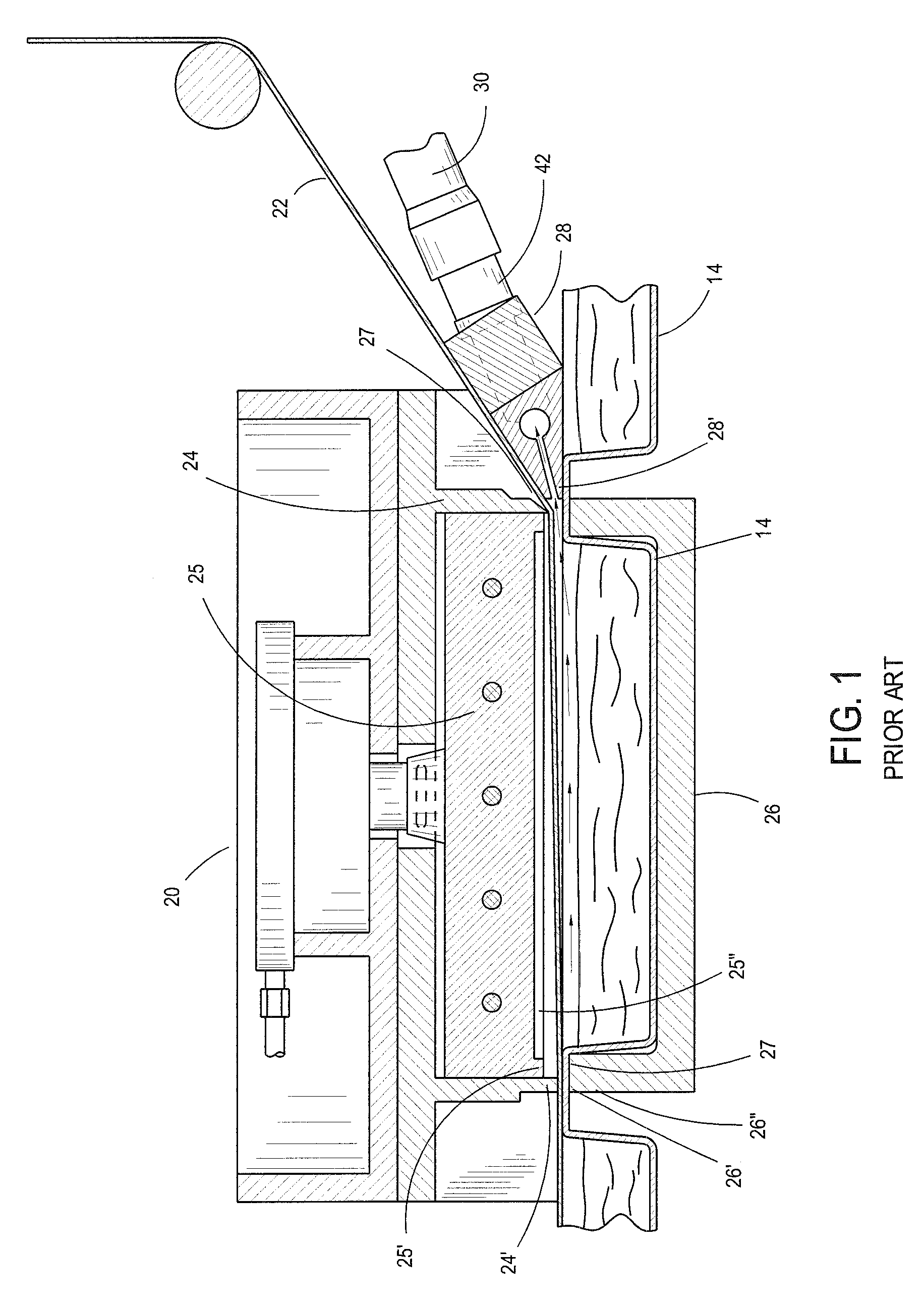
[0014]Referring now to the drawings in greater detail, in FIG. 1 there is shown a prior-art sealing station 20 of a conventional vacuum packaging machine, such as that disclosed in U.S. Pat. No. 5,271,207, which reference is incorporated by reference herein, at which a sealing gasket is used in accordance with the present invention. The sealing station 20 consists of a supply roll 22 of a plastic film 24 constituting the upper layer of the finished vacuum packages and is unrolled to a location juxtapositioned above the product-filled pocket-receptacles. At the sealing station, the upper film is heat-sealed to the lower film, during which sealing a vacuum is formed in the packages via a nozzle-head 28. The sealing station has an upper tool 24 in which is mounted for relative movement a heating tool 25, which heating tool has a lower projecting perimetric, or peripheral, heating element 25′ and one or more transverse heating elements 25″, depending upon the number of vacuum packages i...


PUM

PropertyMeasurementUnit
hardnessaaaaaaaaaa
durometer hardnessaaaaaaaaaa
shapeaaaaaaaaaa

Abstract

An improved sealing gasket for a vacuum-sealing station of a vacuum packaging machine which is made such that the outer perimetric portion thereof is made of a greater hardness than the rest of the sealing gasket, whereby the sealing heat-elements of a reciprocal heating element only substantially contacts against the softer material of the sealing gasket, allowing this softer material to conform to the uneven or non-level condition of the heating element. In the preferred embodiment, the outer-most perimeter of the sealing gasket is made of a greater hardness in the approximate durometer-hardness range of between 60-85 Shore A, while the remainder of sealing gasket is made of less hardness in the approximate durometer-hardness range of between 30-50 Shore A.

Description

BACKGROUND OF THE INVENTION[0001]The present invention is directed to a sealing gasket for a sealing station of a vacuum packaging machine. An example of such a vacuum packaging machine is disclosed in U.S. Pat. No. 5,271,207, which reference is incorporated by reference herein. At the sealing station, the upper and lower film layers forming the horizontal row or rows of filled vacuum-packages are heat-sealed together via an upper heating tool after the rectangular-shaped lower and upper tools of the sealing station have been brought against each other, and after a vacuum has been formed in the each package of the row of packages. The heating tool is lowered toward the upper surface of the outer rim of the lower tool and is supported thereagainst by a sealing gasket mounted by a perimetric groove formed in the upper surface of the outer rim of the lower tool.[0002]The sealing gasket is usually rectangularly-shaped, defining an outer rim and a plurality of inner ribs or cross-members...

Claims


Application Information

Patent Timeline
Patent Type & Authority Patents(United States)
IPC IPC(8): B65B31/00B65B51/14
CPCB65B9/04B65B31/043B65B51/14
Inventor EPSTEIN, MOSHE
Owner EPSTEIN MOSHE
Why Eureka
Try Eureka