Method and device for increasing the rate of the firing cycle of a semi-automatic firearm

a semi-automatic firearm and firing cycle technology, applied in the field of firearms, can solve the problems of limited firing cycle rate of semi-automatic firearms, replete with shortcomings of devices and methods, and inability to increase the firing cycle. the effect of increasing the firing cycl

Inactive Publication Date: 2007-09-25
AW SIM
View PDF15 Cites 27 Cited by
  • Summary
  • Abstract
  • Description
  • Claims
  • Application Information

AI Technical Summary

Benefits of technology

[0007]The present invention relates to a device for increasing the rate of the firing cycle of a semi-automatic firearm that has at least a receiver, a barrel, and a trigger assembly. The device includes a base for supporting the firearm, a trigger extension with a grip attached to the base, and means for removably securing at least the receiver, the barrel,

Problems solved by technology

Hence, the rate of the firing cycle of these firearms is limited by the speed at which the shooter can repeatedly depress, release, and re-depress the trigger.
When the rate of the firing cycle of the automatic is compared to the firing rate of the semi-automatic, one understands that the firing rate of the semi-automatic firearm is typic

Method used


Image

  • Method and device for increasing the rate of the firing cycle of a semi-automatic firearm
  • Method and device for increasing the rate of the firing cycle of a semi-automatic firearm
  • Method and device for increasing the rate of the firing cycle of a semi-automatic firearm

Examples


first embodiment

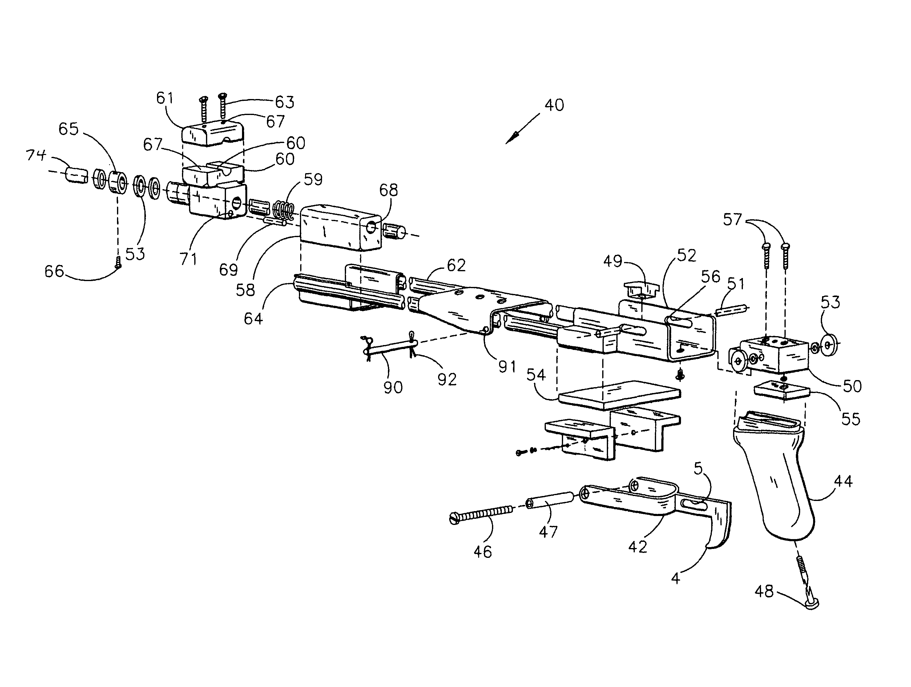
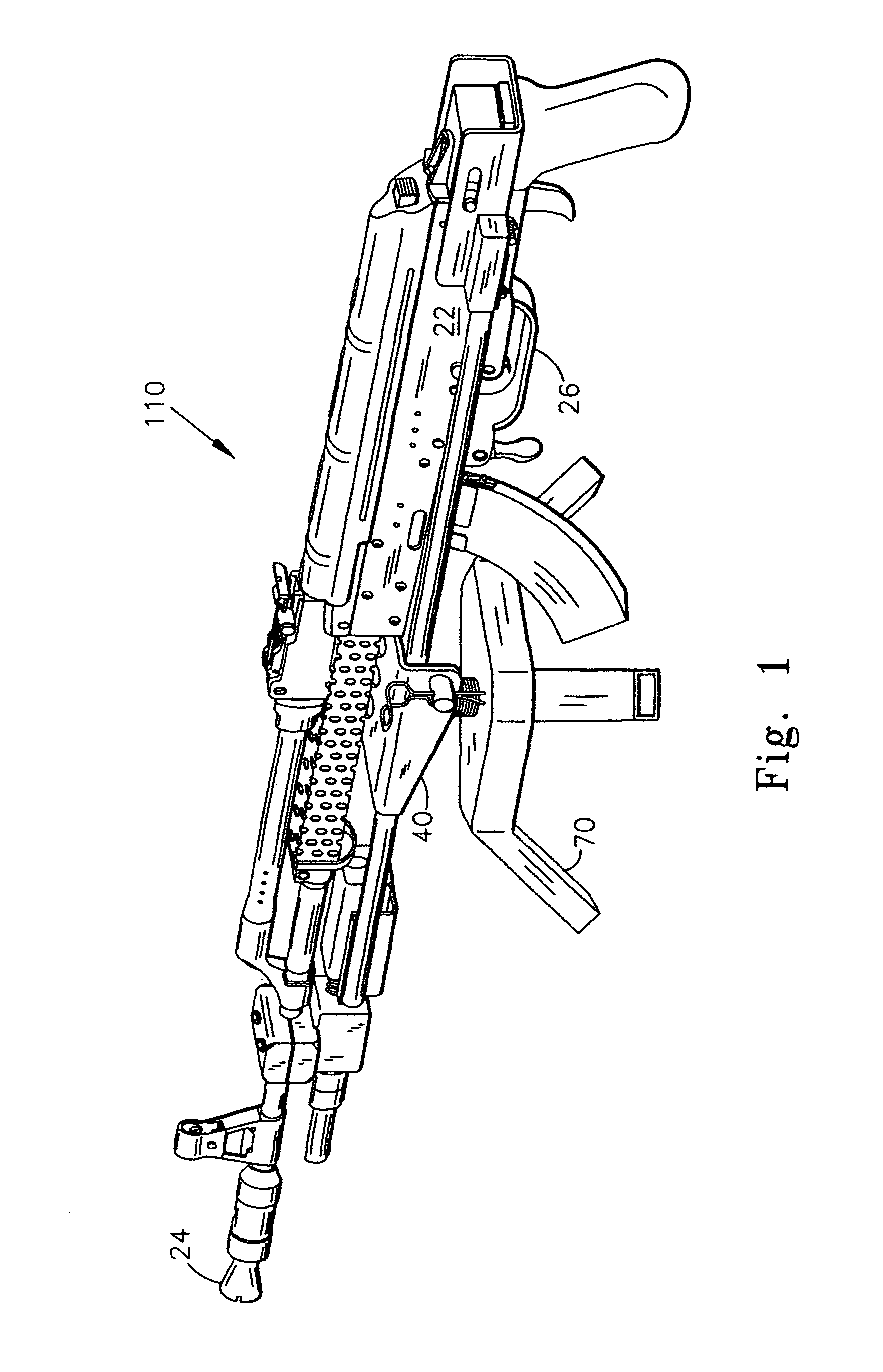
[0025]FIGS. 1-9 relate to the present invention, a method and device for increasing the rate of the firing cycle of a semi-automatic firearm of the long-arm type configuration. The device includes a base 40 for supporting at least the receiver 22, barrel 24, and trigger assembly 26 of a firearm 20. Base 40 is formed from a rigid material such as steel or the like and includes trigger extension 42 and grip 44, as shown in FIG. 4. It should be understood that base 40 and its parts may be formed from materials other than steel. Such materials must be rigid and possess the physical and mechanical properties that make them machinable and suitable for supporting the firearms contemplated by the invention. Base 40 must withstand the forces displaced during discharge of the firearm and during assembly and disassembly, as discussed below.

second embodiment

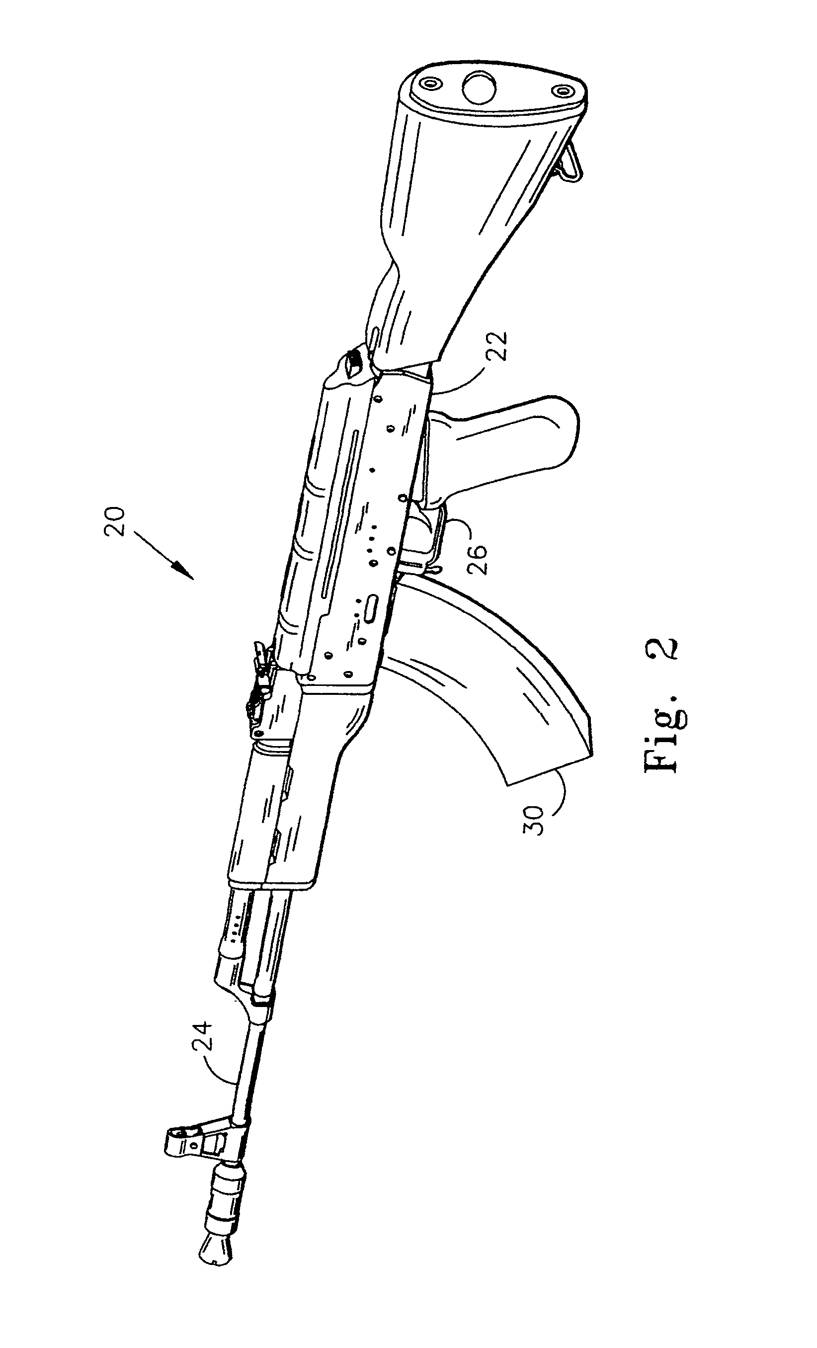
[0026]FIGS. 10-13 relate to the present invention, which relates to a method and device for increasing the rate of the firing cycle of a semi-automatic firearm of the A4 type. Throughout this description, like numerals will be used to identify like parts and features that are common to both of the above-mentioned embodiments.

[0027]With reference to FIG. 4, in a currently preferred embodiment, trigger extension 42 has trigger 4, and grip 44 is a pistol-type grip. The embodiment of base 40 shown in FIGS. 10 and 11 includes trigger extension 42 having trigger 4 and pivot 128. Trigger 4′ has upstanding portion 101. Trigger extension 42 is preferably formed from steel, while grip(s) 44, 125, as shown in FIGS. 4, 10-11, may be formed from wood, plastic or other rigid material.

[0028]Referring to all the FIGS., front end 41 and rear end 43 of base 40 are connected by elongated steel members 62,64. Base 40 includes slide 50, which is housed in slide mount 52. Slide 50 is presently formed fro...


PUM


Abstract

A device and method for increasing the rate of the firing cycle of a semi-automatic firearm includes a base that is adapted to support any one of a variety of semi-automatic firearms. The base includes a trigger extension with a grip, a slide mount, and a slide housed within the slide mount. At least the receiver, barrel, and trigger assembly of the firearm are secured to the base so that they may move as a single unit upon the base between a rearward position upon discharge of the firearm and a forward position. A biasing means continuously biases the receiver, barrel, and trigger assembly upon the base toward the forward position to effect successive discharges of the firearm.

Description

TECHNICAL FIELD OF THE INVENTION[0001]This invention relates generally to firearms and, more particularly, to a method and device for increasing the rate of the firing cycle of a semi-automatic firearm.BACKGROUND OF THE INVENTION[0002]Among the differences between automatic firearms and semi-automatic firearms is the rate of their respective firing cycles. Generally, the firing cycle of a semi-automatic firearm involves the sequential steps of depressing the trigger, releasing the trigger, and re-depressing the trigger. Upon discharge, a semi-automatic firearm typically ejects a spent cartridge casing and sequentially feeds a loaded cartridge into the chamber. The “auto-loading” feature of the semi-automatic does not change the fact that a semi-automatic firearm will not discharge without the sequential release and re-depression of the trigger. Hence, the rate of the firing cycle of these firearms is limited by the speed at which the shooter can repeatedly depress, release, and re-d...

Claims


Application Information

Patent Timeline
IPC IPC(8): F41A19/09F41A25/00F41A3/88
CPCF41A19/09F41A25/14F41A25/22
Inventor ROGERS, STEVE
Owner AW SIM
Why Eureka
Try Eureka