Rack force disturbance rejection

a technology of disturbance and rack force, applied in the direction of steering initiation, instruments, vessel construction, etc., can solve the problems of dangerously affecting the stability of the vehicle, adversely affecting the subjective evaluation of the vehicle, and lateral tyre forces, so as to improve the disturbance force of the steering rack

Inactive Publication Date: 2007-09-25
TRW LIMITED
View PDF12 Cites 17 Cited by
  • Summary
  • Abstract
  • Description
  • Claims
  • Application Information

AI Technical Summary

Benefits of technology

[0041]Advantageously, the steering rack disturbance force (Fdist) is improved by combining with the estimate of steering rack disturbance force obtained via the steering column observer an estimate of steering force disturbance based upon estimated longitudinal tyre force imbalance.

Problems solved by technology

Variation in road surface friction and profile, asymmetric brake torque and differential acceleration of the front wheels cause disturbances in the longitudinal tyre forces, lateral tyre forces, tyre self-aligning moment and suspension deflection forces.
These disturbances are fed to the driver by the steering column affecting subjective evaluation, and in the worst case vehicle instability.
Disturbance forces in the steering system will be transmitted to the driver through the steering column, potentially adversely affecting the subjective evaluation of a vehicle.
Unexpected disturbances can also dangerously affect the vehicle's stability.
Designing steering and suspension geometry with the constraint to minimise the transmission of such disturbances may lead to compromises in other aspects of their design.

Method used


Image

  • Rack force disturbance rejection
  • Rack force disturbance rejection
  • Rack force disturbance rejection

Examples


first embodiment

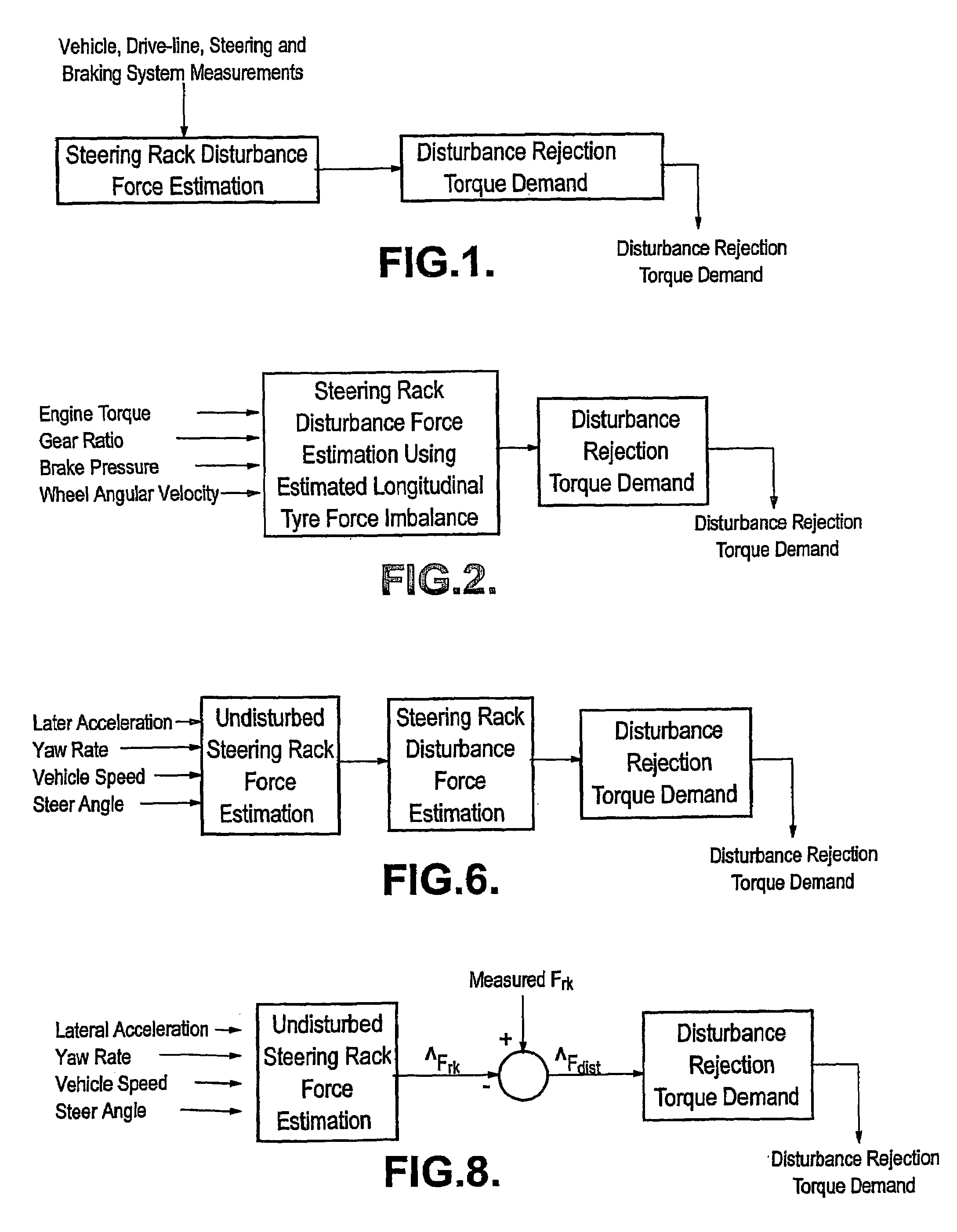
[0058]the control algorithm uses measurements or estimates of the engine torque, brake pressures and wheel speeds to estimate the disturbance due to longitudinal tyre force imbalance (see FIG. 2).

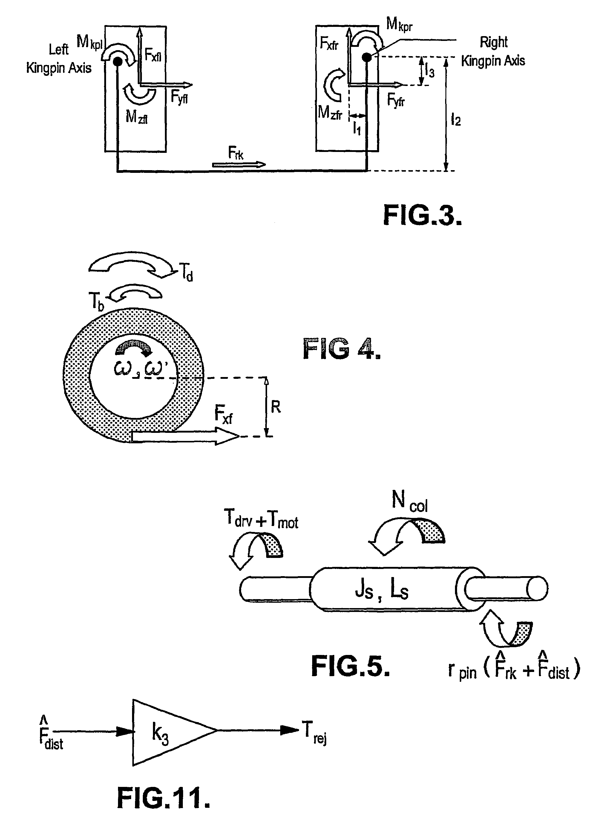
[0059]Steering geometry design commonly has the lines of action of the tyres' longitudinal forces placed so that the forces create a moment about the kingpin axis (see FIG. 3). As the geometry is symmetrical about the longitudinal axis of the vehicle, equal longitudinal forces cause equal and opposite kingpin moments (i.e. they are balanced). Any imbalance in the longitudinal forces will cause an imbalance in the left and right kingpin moments and result in a force which will be passed on to the driver via the steering rack.

[0060]In a FWD or 4WD vehicle the differential splits the engine torque equally between the left and right front wheels. There will be no longitudinal front tyre force imbalance if this equality of drive torque is combined with both wheels having constant angular velocit...

second embodiment

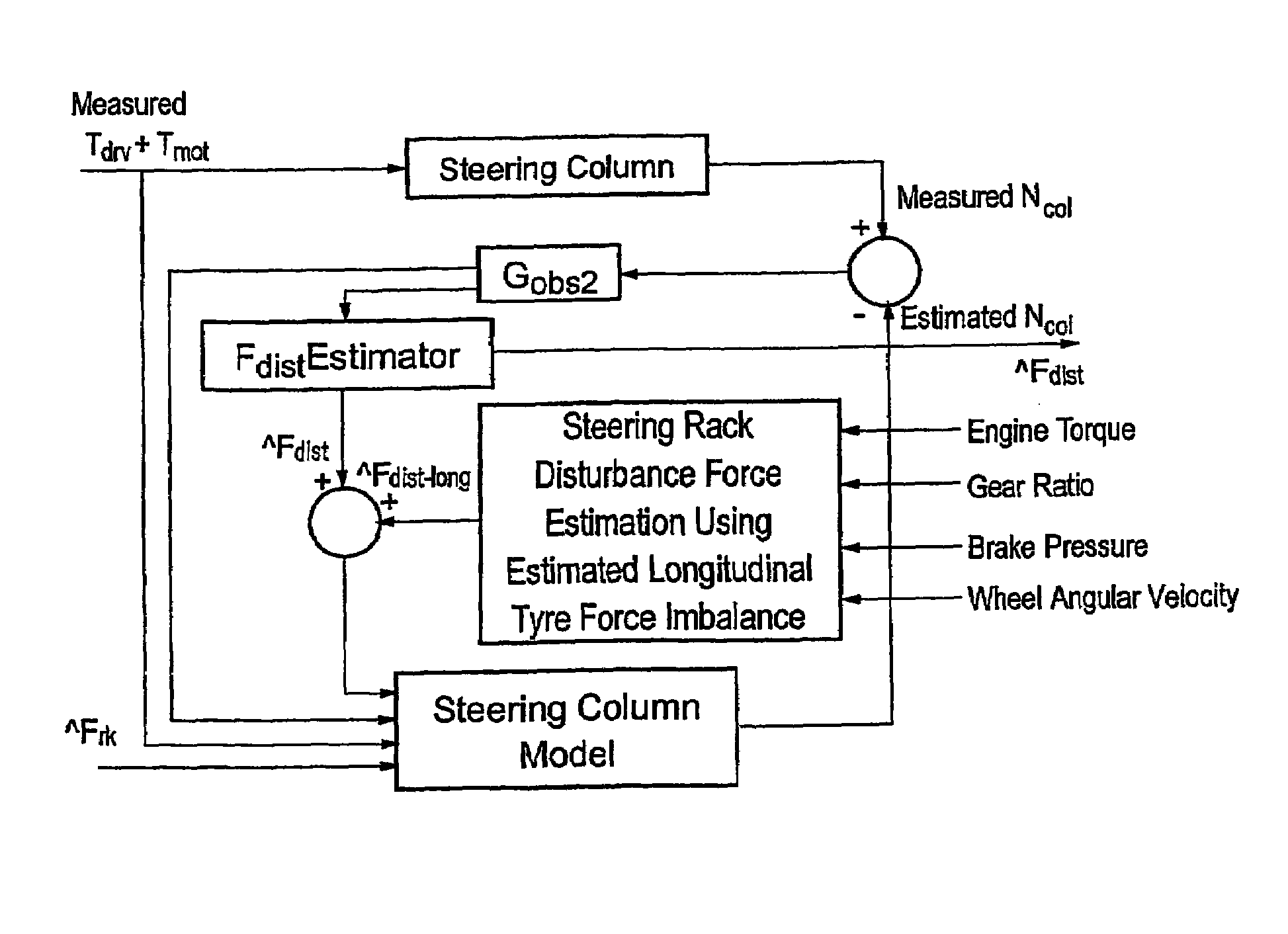
[0070]the control algorithm has three stages (as shown in FIG. 6). It initially estimates the force on the steering rack expected when an idealised, undisturbed vehicle undergoes the actual measured motion of the vehicle (for example its speed yaw rate, lateral acceleration and steer angle). It then calculates the disturbance force on the steering rack using either a measurement of the total force on the rack or an observer of the motion of the steering column using measurements of steering wheel torque, assistance torque and steering column angular velocity. The control algorithm then manipulates the steering rack disturbance force estimate into a demand torque to compensate substantially for the disturbance.

[0071]The first embodiment only considers the effect of longitudinal tyre force disturbances. As previously stated, variation in tyre lateral forces and self-aligning moments and suspension deflection forces can also induce disturbances in the steering rack. The first embodimen...


PUM


Abstract

A road vehicle steering system which is adapted to use measurements and estimates characterising the motion of and forces acting on the vehicle and the steering system such as to derive an estimate of steering system disturbance force and to then use the latter estimate to establish a torque demand for the vehicle electronic power steering (EPS) which substantially compensates for this disturbance force.

Description

CROSS-REFERENCE TO RELATED APPLICATIONS[0001]This application is a continuation of International Application No. PCT / GB2004 / 001356, filed Mar. 31, 2004, the disclosures of which are incorporated herein by reference, and which claims priority to Great Britain Patent Application No. 0308133.8 filed Apr. 9, 2003, the disclosures of which are incorporated herein by reference.BACKGROUND OF THE INVENTION[0002]The present invention relates to the steering of automobiles.[0003]Variation in road surface friction and profile, asymmetric brake torque and differential acceleration of the front wheels cause disturbances in the longitudinal tyre forces, lateral tyre forces, tyre self-aligning moment and suspension deflection forces. These disturbances are fed to the driver by the steering column affecting subjective evaluation, and in the worst case vehicle instability.[0004]The lateral force on a vehicle's steering rack is a function of the sum of the moments about its left and right kingpin axe...

Claims


Application Information

Patent Timeline
Patent Type & Authority Patents(United States)
IPC IPC(8): B62D6/04B62D6/00B62D7/22
CPCB62D6/005B62D7/22
Inventor PICK, ANDREW JAMESSWORN, TIMOTHY JAMESBARTON, ANDREW DENNISFARRELLY, JAMES OWEN PATRICK
Owner TRW LIMITED
Why Eureka
Try Eureka