Abnormal current determining method, electronic apparatus, and computer program of same

a technology of abnormal current and determining method, applied in the direction of emergency protective arrangements for limiting excess voltage/current, wireless communication, substation equipment, etc., can solve the problems of inability difficulty for conventional electronic apparatus to detect an abnormal current with high accuracy, so as to eliminate affection and high accuracy

Inactive Publication Date: 2007-09-25
NEC CORP
View PDF8 Cites 5 Cited by
  • Summary
  • Abstract
  • Description
  • Claims
  • Application Information

AI Technical Summary

Benefits of technology

[0006]The present invention is designed to overcome the foregoing problems. It is an object of the present invention to detect an abnormal current state (i.e. at least any of an overcurrent and an undercurrent) which arises in electronic apparatus, with high accuracy while eliminating affection caused by variations among individual pieces of electronic apparatus.

Problems solved by technology

This makes it difficult for conventional electronic apparatus to detect an overcurrent with high accuracy.
In addition, the conventional techniques have been possible to detect only an overcurrent as an abnormal current, and these techniques could not detect an undercurrent.

Method used


Image

  • Abnormal current determining method, electronic apparatus, and computer program of same
  • Abnormal current determining method, electronic apparatus, and computer program of same
  • Abnormal current determining method, electronic apparatus, and computer program of same

Examples


first embodiment

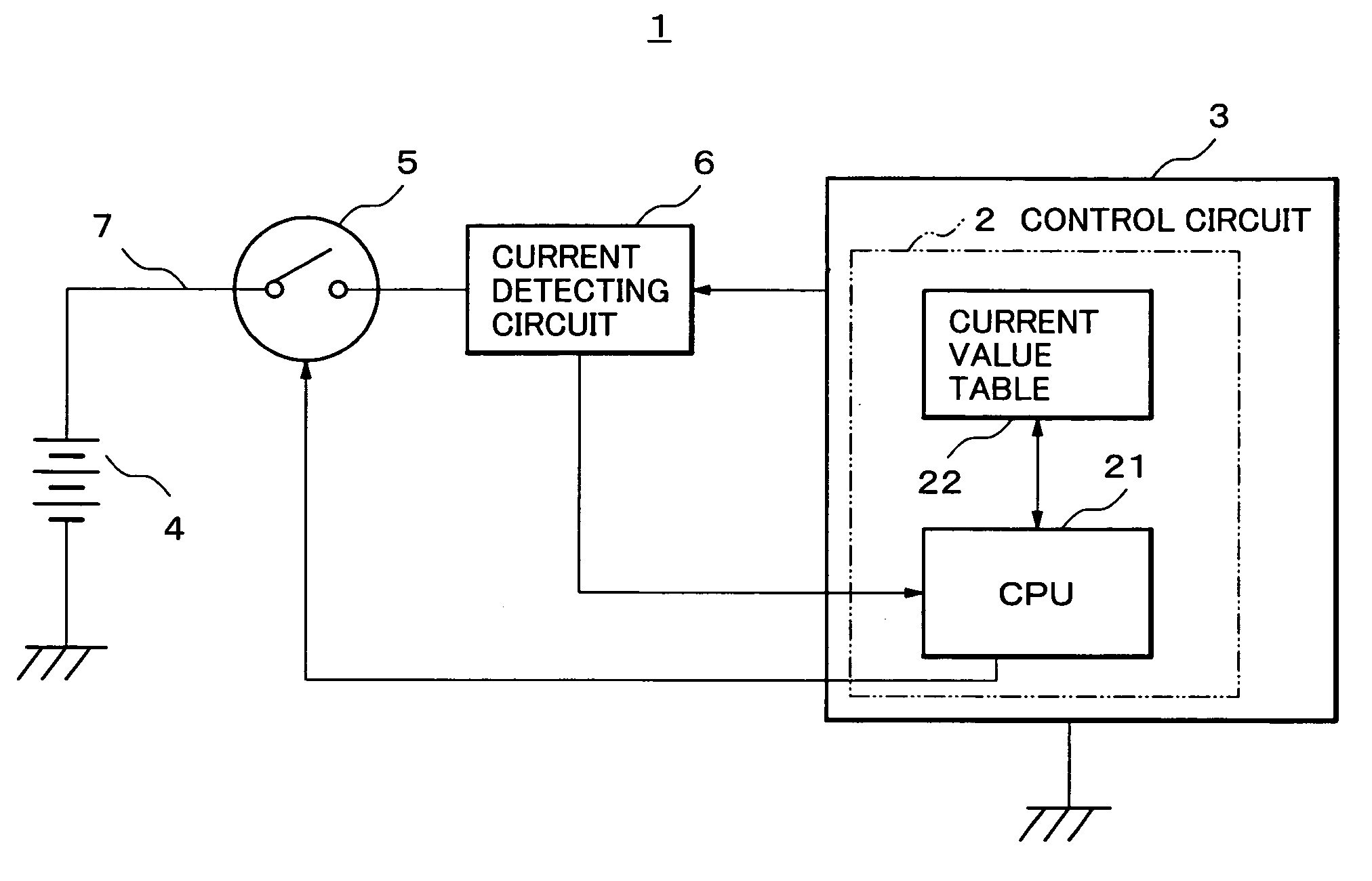
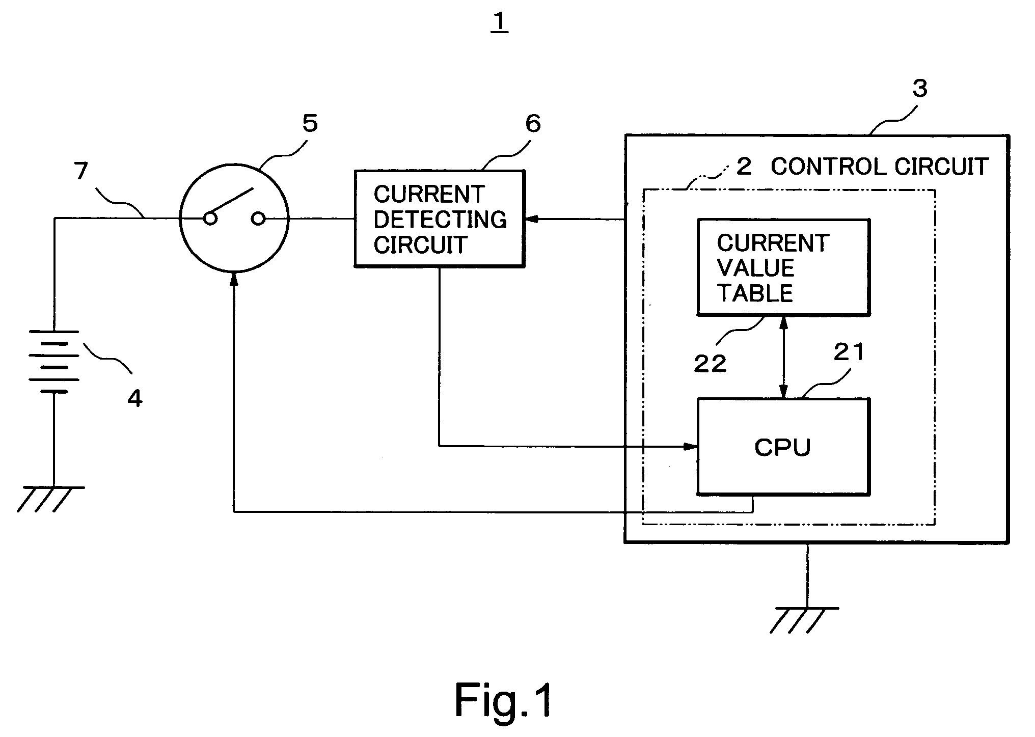
[0027]FIG. 1 is a block diagram making extracts of characteristic constituents of a cellular telephone 1 according to a first embodiment of the present invention.

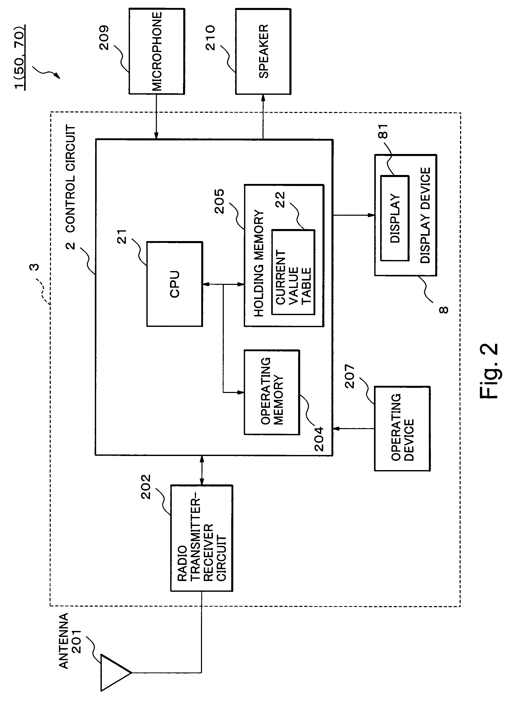
[0028]Firstly, the cellular telephone 1 has communication functions including voice communication, and transmission and reception of electronic mails. Moreover, the cellular telephone 1 is configured to be operable in plural types of operation modes, such as standby status, voice communication status, packet communication status, and electronic mail editing status. The descriptions will be given later with reference to FIG. 2 with regard to the general configuration of the cellular telephone 1, which serves to implement the communication functions and the operations in a plurality of operation modes.

[0029]As shown in FIG. 1, the cellular telephone 1 broadly includes a main unit 3, a power source 4, a power switch 5, and a current detecting circuit 6. The main unit 3 includes a control circuit 2 having a central processing u...

second embodiment

[0086]Next, a second embodiment of the present invention will be described with reference to FIG. 5. FIG. 5 is a block diagram making extracts of characteristic constituents of a cellular telephone according to the second embodiment of the present invention.

[0087]A cellular telephone 50 (FIG. 5) according to the second embodiment is different from the cellular telephone 1 according to the first embodiment only in terms of the points to be described below. Since other aspects of the cellular telephone 50 are similar to those of the cellular telephone 1, like reference numerals designate like constituents and the description thereof will be omitted.

[0088]The cellular telephone 50 has a basic configuration which is similar to that of the cellular telephone 1. However, for the purpose of facilitating the explanation, an assumption will be made herein that the display device 8 be not incorporated in the main unit 3.

[0089]Specifically, the cellular telephone 50 according to the second emb...

third embodiment

Modified Example of Third Embodiment

[0120]The third embodiment has been described in the case where the predetermined margin includes only the margin B and margin E. However, it is also possible to design the predetermined margin to include only the margin B (i.e. the minimum allowance required). Specifically, it is possible to delete the above-described margin E in case of a small variation in voltage among the power sources or when a current variation is hardly observed despite occurrence of the variation in voltage among the power sources.


PUM


Abstract

A cellular telephone 1 measures a current value after being turned on, and performs addition and subtraction of a predetermined margin to and from the measured value, and thereby sets up determination thresholds for an overcurrent and an undercurrent, namely, a minimum current value and a maximum current value, respectively. Here, the predetermined margin includes minimum allowance required (B) as a standard, a variation (E) in voltage of a power source of the cellular telephone 1, and a variation (D) in an operating temperature of the cellular telephone 1.

Description

FIELD OF THE INVENTION[0001]The present invention relates to a technical field of detecting an abnormal current in communication terminals such as cellular telephones and in various types of electronic apparatus.BACKGROUND OF THE INVENTION[0002]Techniques for detecting an abnormal current in various types of electronic apparatus have been heretofore proposed. In such techniques, electronic apparatus subject to detection includes a memory which stores thresholds for determination of an overcurrent in various operation modes of the equipment in the form of a table. The electronic apparatus refers to the table to determine whether or not a measured value of a current passing through the equipment exceeds the threshold for determination corresponding to each operation mode. When the determination is made that the measured value exceeds the threshold for determination, the electronic apparatus determines that the equipment is in an overcurrent state. The above-mentioned techniques are di...

Claims


Application Information

Patent Timeline
Patent Type & Authority Patents(United States)
IPC IPC(8): H02H3/08H02H3/00H02H3/087H02H3/12H04M1/24H04M1/724
CPCH02H3/006H04M1/24H02H3/087H02H3/12H04M1/72519H04M1/724
Inventor OGAWA, RYUTARO
Owner NEC CORP
Why Eureka
Try Eureka